IEC 60851-5 Winding Wires – Electrical Property Test Methods
With electric propulsion becoming a recognized viable technology for aerospace, it is essential to understand the technologies that support these new devices. While electric propulsion is nothing new, its successful application for aerospace requires that the hard lessons learned on the proper installation, maintenance, and design of aerospace systems are not forgotten.
One component critical to just about every electric motor is the motor windings. How these are designed, tested, and verified is important for this next generation of electric propulsion.
What are Winding Wires?
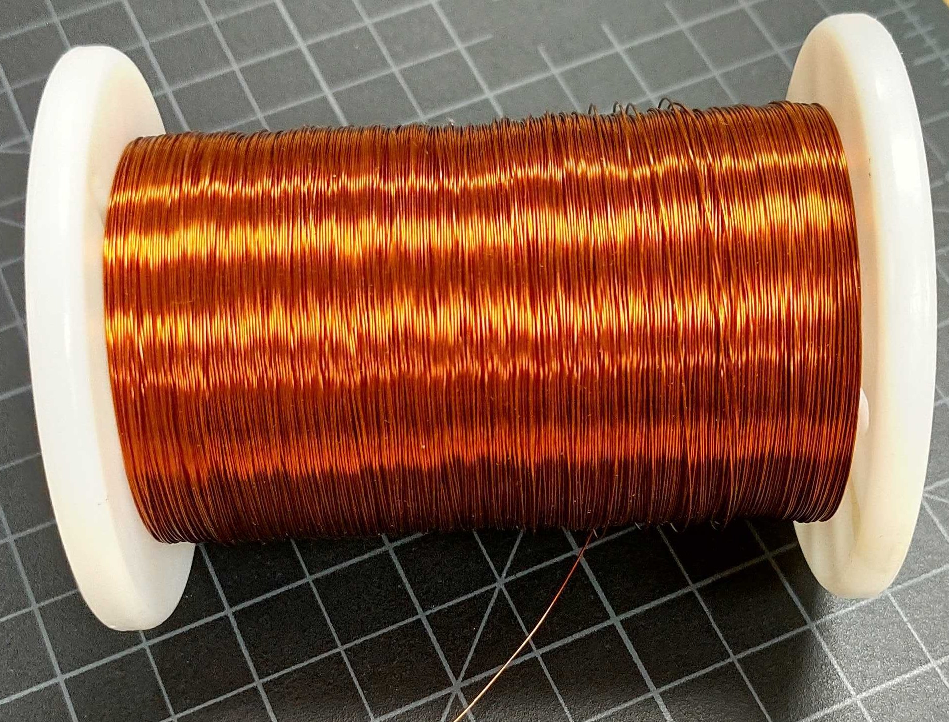
Winding wires, or magnet wires, are the wires used to construct coils in electronic components (transformers, relays, etc.) that generate the component’s magnetic field. These wires are primarily composed of a copper or aluminum conductor with a very thin layer of insulation. The insulation layer is as thin as possible to keep the wire cross-section small making it possible to squeeze the highest number of windings in the motor. Whereas most electrical wires are cylindrical, winding wires often have a rectangular cross-section profile; this allows for maximum cross-section during winding, thus reducing potential losses.
IEC 60851-5
Due to the vast differences in application and construction, a different set of requirements for winding wire is required rather than those applicable to general use electrical wire for Electrical Wiring Integration systems (EWIS). The IEC60851 series of standards covers tests specifically for winding wires.
This article discusses the standard IEC60851-5, the section on electrical tests, and, where applicable, compares these methods to similar methods identified in AS4373, a commonly used testing standard for general-use wire in aerospace applications.
Tests Covered
Electrical Resistance
As the name suggests, the electrical resistance test is a simple DC resistance measurement made on a 1 m segment of wire at room temperature (20oC). The test, as described in IEC 60851, does not specify the exact method of measurement, but requires the method used to be accurate to within 0.5%.
The comparative test from AS4373 is method 403, conductor resistance, in which specimens are tested with either a Kelvin or Wheatstone bridge to an accuracy within 0.2%. One may conclude that this method may also be applied to winding wire, as a specific procedure is unspecified in IEC 60851-5 and the accuracy margin is within that defined for winding wire.
Breakdown Voltage
Several different methods/ configurations for different sizes and construction of wire are addressed in the IEC 60851-5 document but each of the tests follows the same general principle.
- The specimen is placed in contact with a conductive metal electrode or is twisted around itself such that two independent segments of the same wire act as the test electrodes
- Voltage is applied between the specimen and electrode, increasing at a specified rate.
- An attached detection circuit monitors for leakage current in excess of 5 mA.
- The voltage measured at the time leakage current is detected is recorded as the dielectric breakdown voltage.
For each test configuration, five specimens are tested and one measurement from each specimen is recorded.
This test shares similarities with the wet dielectric test of AS4373; both tests apply a voltage between the wire conductor and an electrode to determine the insulation’s ability to withstand such voltage application. The primary differences between the test methods are the secondary electrode and the magnitude of voltage application. The secondary electrodes used for the winding wire test vary but are always metal, whereas the second electrode in the wet dielectric test is a saltwater bath.
The voltage application in the winding wire test is slowly increased until failure is detected and the voltage application in the wet dielectric test is slowly increased to a specified value.
Continuity of Insulation
The IEC 60851-5 defines continuity of insulation as the “number of faults per length of wire detected by means of an electrical test circuit.” The test method identified in the standard is similar to the AS4373 method 505, spark test, used on typical EWIS wire.
For winding wires with a nominal diameter up to 0.05 mm, the specimen under test is sandwiched between two felt pads that have been saturated in an electrolytic solution. The specimen is slowly pulled through the two pads while a detection circuit monitors for faults – sections of the specimen where the measured resistance is below the specified value. Each occurrence of a fault is counted, and the number of faults detected over a 30 m segment of wire is reported.
Winding wires larger than 0.05 mm in diameter are tested similarly, but the fixture consists of either a graphite brush or a grooved electrode rather than the two felt pads.
The AS4373 method is functionally very similar to the IEC 60851-5 method. One of the main differences is in the test fixture; the AS4373 method primarily utilizes a bath of metallic conductive beads as the external electrode. The AS4373 method also uses an AC voltage whereas the IEC 60851-5 utilizes a DC voltage for testing.
Dielectric Dissipation Factor
Dielectric dissipation factor is a measure of a material’s inefficiency as an insulator. This characteristic is measured at a defined frequency for a material. A low dissipation factor for a material indicates that it is a more efficient insulator, whereas a high dissipation factor indicates a less efficient insulator.
To measure the insulation’s dissipation factor, the wire is placed into a test fixture such that the insulation is in contact with an external conductive material. In this configuration, the internal wire conductor and the external conductive material act as the plates of a capacitor.
This testing may be performed either in a metal electrode bath or using a conductive suspension electrode. The dissipation factor is read directly from an impedance meter.
Though AS4373 does not include dissipation factor measurement, the ASTM D150 standard. ‘AC Loss Characteristics and Permittivity (Dielectric Constant) of Solid Electrical Insulation’, requires measurement of the dissipation factor as part of its evaluation of electrical insulation. Here, the dissipation factor is one of many properties measured regarding the insulation’s effectiveness.
Pin Hole
The pin hole test is essentially a visual examination after a specific conditioning sequence. Specimens are subject to a brief oven exposure, an aqueous NaCl exposure, and one minute of voltage application (parameters for these each are defined by the composition and size of the wire under test). During the voltage application, a 500mA short-circuit limit is maintained to avoid excessive heating. After the full barrage of conditioning, the specimen is visually examined for any pin holes that may have formed, and the number observed is reported.
The purpose of pin hole testing is to evaluate the effect of the NaCl solution on the wire’s insulation. This is comparable to AS4373’s wet dielectric voltage withstand test in which specimens are submerged in a saltwater solution and evaluated for any flaws in the insulation. The wires in the AS4373 test soak in the saltwater solution for 4 hours, after which time a voltage is applied between the wire conductor and the water bath. The circuit is monitored for any leakage current through the insulation.
Though both tests evaluate a wire for insulation flaws when exposed to saltwater, the AS4373 method is more thorough because leakage current may occur from insulation flaws too small to be seen with the naked eye.
Conclusion
Winding wires are critical for the functionality of many electrical and electronic components. While the winding wires are used for an application different from standard airframe wire, their assessment techniques share a high degree of similarity. It is imperative that their electrical properties are sufficient to ensure reliability in the more extensive electrical system as a whole. For guidance on winding wire applications and relevant testing, contact Lectromec today.