There are some properties that are taken for granted with wires and cables until they are needed for precision applications. A conductor’s conductivity is assumed until the impact of a voltage drop or heating must be determined. In the same way, a cable’s dielectric constant is uninteresting until the integrity of high-frequency signals becomes critical.
This last property (dielectric constant), is important not only for cable insulations but also for a wide range of applications.
Test Overview
The dielectric constant is a measure of the ratio of a material’s capacitance compared to the same configuration measured in a vacuum. Various methods can be employed to measure this value and are dependent on the geometry of the samples in question.
Test Methods
The most common standards for determining the dielectric constant for a sample are ASTM D150 and AS4373 Method 501. The ASTM D150 standard is used to determine various properties of a dielectric material, such as the dissipation factor and loss index, where the AS4373 standard focuses on just the dielectric constant of a wire sample’s insulation.
ASTM D150
The ASTM standard requires the dissipation factor to be reported. The dissipation factor is the ratio of the dissipated energy versus the stored energy on any given cycle for a specified frequency. Materials with a high dissipation factor are less likely to hold energy and do not perform as well when used as an insulator. A standard capacitor can be separated into an ideal capacitor and a resistor, with either a series representation or a parallel configuration as seen in the figures below. These values can be measured and are related to the dissipation factor (D) and frequency (f) by the equation:
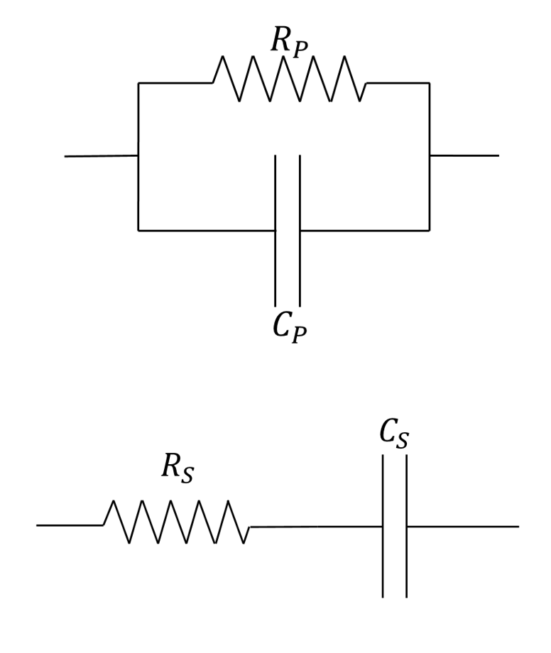
Parallel circuit [top] and series circuit [bottom] representation.
The dissipation factor can also be related to the angular difference in voltage applied to the dielectric and the component of the resulting current having the same frequency as the voltage, otherwise known as the phase angle (θ). This can be seen in the equation:
Another value that can be determined from this standard is the power factor, which is the ratio of the power (W) dissipated in a material to the product of the voltage and current. This can also be related to the phase angle in the following equation:
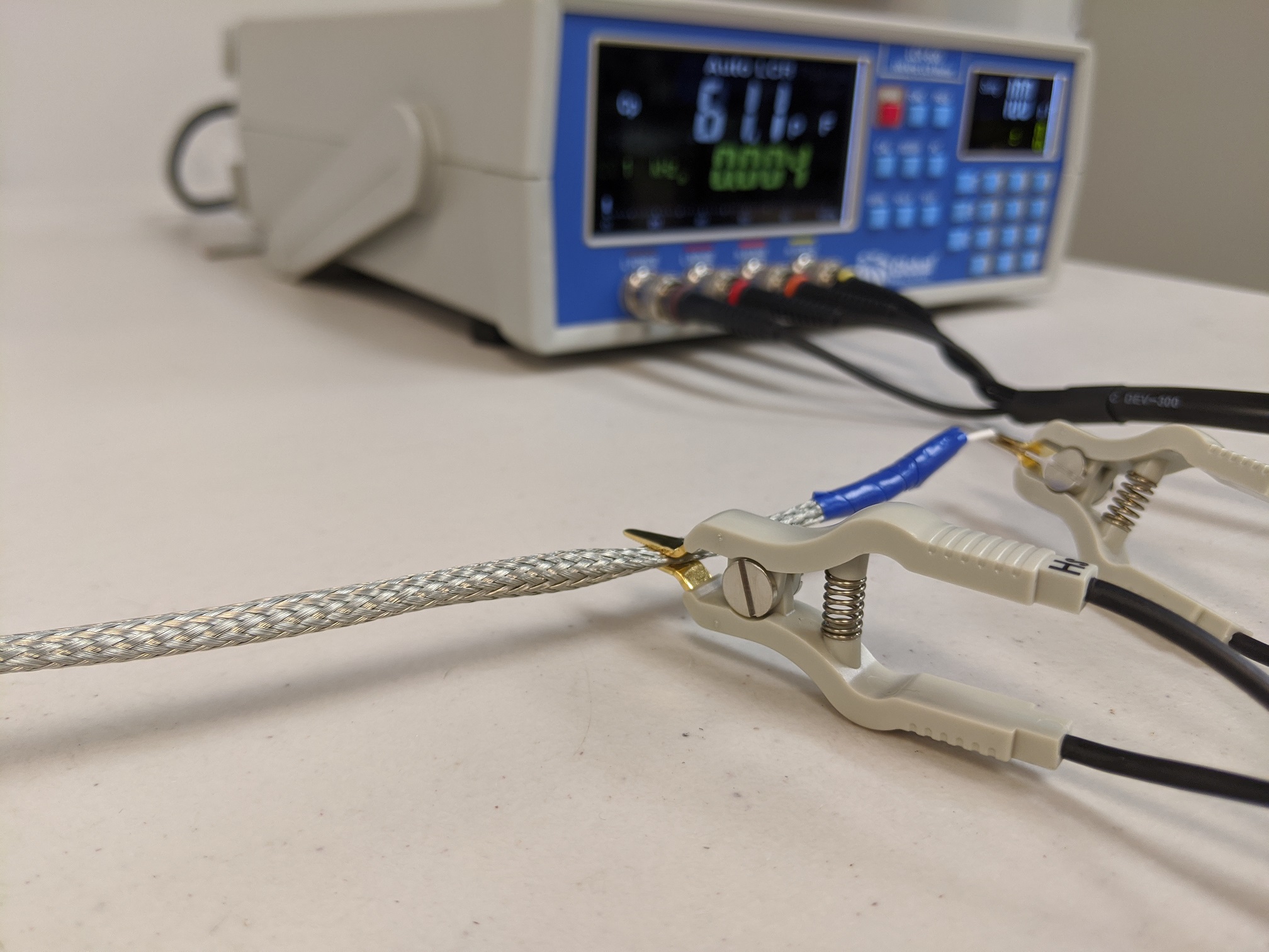
The ASTM D150 standard requires materials to be cut or molded to a suitable shape and thickness determined by the material specification or ASTM D374 if the material is unknown. For Lectromec’s testing, we requested for our samples to be between 1/32 inch (0.794 mm) and 1/8 inch (3.175 mm) thick. Electrodes then can be machined such that the specimen extends beyond the electrodes by at least twice the thickness of the specimen. Gels can also be tested for this standard by compressing the gel until the required separation distance is achieved. Multiple methods can be employed to measure a material’s capacitance and the AC loss characteristics. At Lectromec, we use two parallel plates of equal surface area. These electrodes are then connected to a high-precision 100 kHz LCR meter. This equipment reports the applied frequency, capacitance, and dissipation factor.
From the output of the LCR meter, we can determine the dielectric constant by taking the parallel capacitance and the expected capacitance ratio of the configuration when the dielectric is replaced with vacuum (Cv). For a parallel plate capacitor, the formula is:
where \(\mathrm{\varepsilon }_{0}^{}\) is the permeability of free space, A is the surface area of the electrodes, and d is the plate-to-plate separation distance, which should be equal to the thickness of the material being tested. Therefore, the dielectric constant is given by:
Dielectric testing for some components is easy and straight forward. However, as the geometry becomes more complex, so to does the calculation and means for testing.
AS4373 Method 501
In the AS4373 test procedure, a 22 AWG wire sample that is at least 15 feet (4.6 m) long has its middle 10 feet (3.05 m) submerged in a grounded bath of distilled water, while at least 2.5 feet (0.76 m) of each end of the specimen is kept above the surface to prevent any edge effects from being introduced. The capacitance (C) is then determined at a frequency of 60 Hz or 1000 Hz using a voltage that is no greater than 40 V per 0.001 inches (0.0254 mm) of insulation. To determine the dielectric constant (relative permittivity), the sample is treated as a cylindrical capacitor. The conductor diameter (B) is determined using Method 401 of AS4373 and the insulation diameter (A) is measured using Method 901 of AS4373. With these values, the dielectric constant can be determined from the equation:
where the capacitance is measured in microfarads.
In Application
Dielectrics can serve two functions in testing. The first application is to serve as an insulator aiding in protecting electrical components from one another and prevent an undesired path to ground. The second function of dielectrics is to increase the capacitance of a capacitor. For parallel plate and cylindrical capacitors, the dielectric constant is linearly correlated to the capacitance, so materials with higher dielectric constants are recommended for applications where smaller components are desired.
Conclusion
There are several techniques for determining a material’s dielectric constant, and each of these are necessary to accommodate the various geometries and types of materials. Furthermore, the secondary parameters that are captured during a material’s dielectric constant evaluation (e.g. dissipation factor) can be of value to those seeking the best material for their application.
For those in need of material or component testing, Lectromec’s ISO 17025:2017 accredited lab has the knowledge, experience, and tools that are needed to get accurate data for your application. Contact us to find out more.

Chris Wollbrink
Engineer, Lectromec
Chris.Wollbrink@lectromec.comChris has been with Lectromec since 2019 and has been a key contributor on projects involving testing of EWIS/fuel system failure modes, the impact of poor installation practices on EWIS longevity, and wire/cable certification testing. His knowledge and attention to detail ensure consistent delivery of accurate test results from Lectromec’s lab.