Key Takeaways
- Velocity of propagation is the speed at which an electromagnetic signal moves along a transmission line relative to the speed of light in free space.
- The conductor defines the boundary conditions and return path; the dielectric and geometry define where the field exists.
- The dominant variables of cable performance regarding velocity of propagation are dielectric constant, field geometry, and return-path structure.
The speed of light in a vacuum is an accepted, incontrovertible truth of our universe, but the velocity of signal propagation down a cable is not. If low-latency systems are the key, then optimizing parameters in electrical signal cable applications is paramount. For the application engineer, looking to determine what combination of wires, insulation, geometries, and shielding yield the best performance is also important. In this article, we review the concept of velocity of propagation, where it impacts system design, and the practical design factors for cable constructions.
What is Velocity of Propagation?
Velocity of propagation is the speed at which an electromagnetic signal moves along a transmission line relative to the speed of light in free space. It is commonly expressed as a velocity factor, such as 66%, 70%, or 85% of c. In practice, this value determines the time delay through a cable, the electrical length of an interconnect, phase matching requirements, and the timing margin available in high-speed digital links, RF systems, phased arrays, radar, and time-critical aerospace networks.
The first-order transmission-line relationship is straightforward. For a low-loss line, phase velocity is approximately:
where
- \(v\) is the velocity of propagation
- \(L′\) is inductance per unit length, and
- \(C′\) is capacitance per unit length.
In a homogeneous coaxial or twinaxial cable, this reduces to a dependence on the permeability and permittivity of the material surrounding the conductors. For most cable insulation systems, relative permeability is close to 1, so the controlling variable becomes the effective dielectric constant. This is why the practical approximation is often written as:
where \(ε_{eff}\) is the effective dielectric constant seen by the electric field.
The Conductor Metal is Not the Primary Speed Control
A common misconception is that a signal moves “through” the copper conductor the way current flows through a DC circuit. At RF and fast edge rates, the useful picture is different: the signal energy is carried by the electromagnetic field around and between the conductors. The conductor defines the boundary conditions and return path; the dielectric and geometry define where the field exists.
For that reason, swapping a copper conductor with silver, aluminum, or nickel-plated copper does not normally create a large change in velocity of propagation if the dielectric and geometry are unchanged. The metal’s conductivity primarily affects series resistance and conductor loss. Those losses can alter the propagation constant, but in a good low-loss transmission line, the change in phase velocity is generally a second-order effect compared with dielectric choice.
That does not mean the conductor can be ignored. The conductor material affects attenuation, current-carrying capability (ampacity), corrosion behavior (oxidation, fluid exposure, galvanic corrosion, etc.), mechanical durability (e.g., flexing), termination design, and long-term stability (e.g., thermal cycling). In applications where insertion loss, phase stability, or power handling are critical, conductor selection remains an important part of cable engineering.
Dielectric and Geometry
A dielectric’s effect can be seen in common coaxial cable velocity values. For cables that use a solid polyethylene dielectric, the velocity of propagation (VoP) is 66%; other cables dielectrics such as solid PTFE are commonly near 70%, and foamed dielectric constructions will be close to 80%. Looking at the impact on signal transmission, the impact is measurable. A 10-meter cable with a 66% VoP has a one-way delay of about 50.5 ns. At 85% VoP, the delay decreases to about 39.2 ns (a change of about 11 ns 10m). By contrast, changing from copper to silver in the same geometry is unlikely to produce a comparable velocity change; it is more likely to show up as a small loss improvement.
The cable geometry matters because it has a direct impact on the capacitance, inductance, impedance, and field distribution. In a coaxial cable, the center conductor diameter, shield diameter, dielectric material, and air fraction determine impedance and velocity. In twisted shielded pairs, lay length, spacing, insulation thickness, shield proximity, and pair-to-shield capacitance all influence delay and skew. In high-speed digital links, small changes in pair geometry can matter more than a change in conductor metal.
Conductor Material
A conductor material’s largest electrical impact is attenuation. At high frequency, skin effect pushes current toward the conductor surface. Skin depth depends on frequency, permeability, and conductivity. Higher conductivity reduces surface resistance; higher permeability reduces skin depth and can increase loss. This is why silver-plated copper is attractive for microwave conductors, while magnetic or high-loss platings require caution.
Design Variable |
Primary Impact |
Conductor size |
DC resistance, RF loss, heating |
Conductor metal/ plating |
RF loss, corrosion, temperature capability, coefficient of thermal resistance, solderability |
Shield design |
Return path, EMI control, transfer impedance, weight |
Cable geometry |
Impedance, delay, skew, attenuation |
Dielectric constant/ air fraction |
Velocity factor and delay |
Copper remains the default conductor because of its high conductivity, availability, manufacturability, and termination compatibility. Silver plating can reduce RF surface loss and improve oxidation stability when the plating thickness is sufficient relative to skin depth. Aluminum may be selected for weight reduction, often in shields or outer conductors, but its lower conductivity must be considered. Stainless steel or high-strength alloy conductors may be selected for mechanical reasons, but they are generally poor choices for minimum RF loss unless the construction is specifically engineered around that limitation. The other conductor types (nanotube, metalized fibers, copper alloys, copper clad aluminum, etc.) each have their benefits and may find ideal applications in signal cables.
Application Impact
In low-latency systems, velocity of propagation affects synchronization. In phased arrays, cable delay translates directly into phase error, and in differential high-speed data links, unequal delay between pairs becomes skewed. In RF test systems, cable phase stability with flexure and temperature may be as important as initial delay. While it is unlikely that a cable would have multiple conductor types, there is both a technical and practical reason why it is not done.
In aerospace EWIS, cable selection is rarely based on propagation speed alone; the cable must also meet weight, routing, flammability, smoke, toxicity, shielding, voltage, environmental, and maintainability requirements. For most aerospace cable design problems, the correct order of operations is:
- Define the system timing and signal-integrity requirements,
- Select the transmission-line family, impedance, dielectric system, shielding approach, and conductor construction
Hopefully it is clear that optimizing the metal before selecting the dielectric is usually the wrong sequence.
Verification
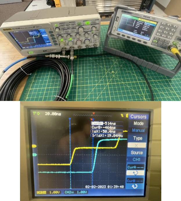
The yellow trace shows the signal propagation down a shorter length of cable compared against the longer cable (blue trace). The time difference between the two cables can be measured and speed of propagation calculated.
Velocity of propagation can be measured using time-domain reflectometry (TDR) or vector network analysis (VNA). TDR is particularly useful because it sends a fast edge into the cable and evaluates reflections caused by impedance changes; the time location of those reflections is used to infer distance and delay. Alternative methods include sending a split signal down two cables of unequal length and measuring the arrival offset of the two signals.
Conclusion
When looking to assess performance, the conductor metal has a real but usually secondary effect on signal propagation speed in an electrical cable. The dominant variables are dielectric constant, field geometry, and return-path structure. Factors where the conductor material will have an impact are attenuation, temperature capability, corrosion behavior, mechanical performance, termination compatibility, and long-term stability. For low-latency cable design, the best path is not simply “use a better metal”; it is to engineer the electromagnetic field path by selecting the right dielectric and geometry, then choose the conductor system that preserves that performance in service.
Contact Lectromec to find out more about cable testing in our ISO 17025:2017 accredited lab.

Michael Traskos
President, Lectromec
michael.traskos@lectromec.comMichael has been involved in the field of EWIS for more than two decades and has worked on a wide range of projects from basic component testing, aircraft certification, and remaining service life assessments. Michael is an FAA DER with a delegated authority covering EWIS certification, the former chairman of the SAE AE-8A EWIS installation committee, and current vice chairman of the SAE AE-8D Wire and Cable standards committee.