Key Takeaways
- The idea of skin effect is that as the frequency on a conductor increases, more of the electrical energy is carried through the area closer to the skin of the conductor.
- As higher frequencies are used, the skin effect reduces the amount of conductor that is used which has an effect of increasing the resistance of the conductor.
- Skin effects are less pronounced on multi-stranded conductors as each strand may be considered an individual conductor.
Introduction
An area of power transmission that we have not talked about in any Lectromec article thus far is the impact of skin effect. While this is an area that is well documented and understood for signal/data cables, the impacts in the area of power cables have been generally ignored. However, as power systems embrace new power technologies, skin effect starts to creep in to have a noticeable and measurable impact. In this article, we discuss what skin effect is and its impact.
Skin Deep
The idea of skin effect is that as the frequency on a conductor increases, more of the electrical energy is carried through the area closer to the skin of the conductor. This occurs due to Eddy currents inside the conductor responding to the rapid changing current that occurs in AC applications. In high frequency applications, the signal is carried entirely in the plating of the conductor whereas with low frequency, most of the conductor is used to carry the power.
The skin depth formula: \(\delta=\sqrt[]{\frac{2\rho}{\omega\mu}}\) which takes in the parameters of the conductor resistivity ‘ρ’, angular frequency ‘ω’, and permeability of the conductor ‘μ’.
Conductor Resistance
At the introductory level, the resistance of a conductor is straightforward. Based upon the standard properties of copper or in the case of smaller gauge wires, high strength copper alloy, to estimate the resistance of a wire, simply take the known resistance of the copper and multiply it by the length of the wire. From a generalized perspective the resistance for a length of copper can be written as: \(r=\frac{\rho*l}{A}\) where ‘r’ is the resistance, ‘ρ’ is the resistivity of the copper or whatever material is used as a conductor, ‘l’ is the length, and ‘a’ is the cross-sectional area.
For standard utility power of 50 or 60Hz, one can find that the skin depth is relatively high. But as higher frequencies are used, the skin effect reduces the amount of conductor that is used which has an effect of increasing the resistance of the conductor. Looking at the equation above, as the cross-sectional area decreases the resistance of a conductor increases. Further implications of the formula are that with higher frequencies the resistance also increases. For solid round conductors the resistance can be approximated with \(R_{ac}=\left(96*d*\sqrt{f_{MHz}}+0.26 \right) *R_{dc}\). Where d is the conductor diameter in inches and the frequency is in megahertz.
Higher Frequency Power
For those power applications seeking to use higher frequency power systems, the consequence is that larger power carrying wires have more of the power being transmitted through the skin and less through the bulk of the copper. Of course, the question behind this is if a system is using a large conductor, then why go to high frequencies?
This can have a significant impact on thermal heating of wires and wire bundles. The AS50881 has a standard model for wire heating and thermal derating of wires that has been in use for quite some time. But with the use of different and higher frequency power systems, those curves no longer accurately reflect the current carrying capabilities of wire gauges. For example, starting with a standard AS22759/87 wire that is 8 AWG, in ambient conditions, it has a current carrying capability of 140A (this is a single conductor running at 200C – not recommended for most applications). Now this is assuming a 400Hz power system. Assuming a three kilohertz power system, and the current carrying capability changes the results.
First, start with the skin depth and estimate the conductor resistivity. At 400Hz, the skin depth comes to 3.2mm (for a solid 8AWG conductor, this includes the entire conductor); when looking at 3kHz, the skin depth drops to 1.19mm. As a quick back of the envelope estimation yields that the high frequency uses about 8% less of the conductor at the 3kHz than at 400Hz. This may not seem like much, but this can results in greater heating of the conductor and the need to upsize to the next wire gauge.
The impact is less pronounced with stranded conductors as each conductor strand can be considered, for the purposes of estimation, as an individual conductor. This means that the skin depth should be factored for each strand, and for most aircraft applications, the skin depth has a negligible effect on conductor resistance. The more contact between strands breaks this estimation and the conductor acts less like a set of individual strand, such as Lizt cables, and more like a single core conductor.
Wide frequency power systems are not immune to skin effects. In these systems, the power frequency is subject to change based on the current state of the engines. This dynamic power frequency means there is also a dynamic conductor resistance. From a system design the question is if the EWIS should be built for the steady state conditions and accept the additional stresses during the brief durations during takeoff where the frequency will be the highest.
Pulse Width Power Resistance
Further, the impact that needs to be discussed is pulse width modulation. Pulse width modulation is a very popular technology. While this does allow for high frequency control and precision control of electronic motors, it does create challenges on the wiring system. The reason behind this is that the pulse width modulated signal is not simply a DC signal. Using a Fourier analysis of the square wave, it is possible to see that the square wave can be represented with a combination of low and high frequency waves that can be used to estimate the different resistance values of the conductor through the waveform.
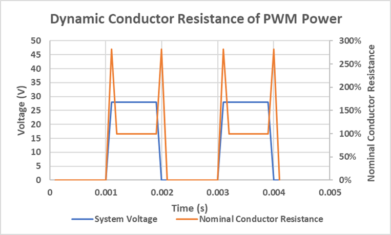
In this example, we take a square wave for a 28 volt system. In the pulse width modulated signal for this example, the signal is on for 0.001 seconds then turns off for 0.001 seconds and repeated (i.e. a 500Hz signal with a 50% duty cycle). Assuming a 0.1ms rise and fall time, this suggests a 40kHz transition at the start and end of each pulse.
Pulse Width Modulation (PWM) creates dynamic wire resistance. This means a more complex thermal modeling of the wiring system.
If we now take these frequency components and consider the high frequency elements during the leading and trailing edges of the on-pulse, it is possible to estimate the dynamic nature of the conductor resistance through the duty cycle. Using the skin depth formula yields an estimated skin depth of 0.32mm. If the 8AWG conductor evaluated above is used, during these transition periods the resistance increases by more than 280%.
In this example, the on-off transitions count for about 20% of the total duration the power is applied. While this is not an exact representation of the conductor resistance, it does show that the resistance of the conductor is not uniform. This will certainly have an impact on design, selection of components, and the needs of thermal management.
The higher frequency power elements and their impacts on wire conductivity, i.e. the skin effect, are part of the reason why wires and cables are typically not supplied with current carrying capabilities. Given the wide range of applications and uses of wires, it is impossible for a wire manufacturer to provide an accurate estimation of the current carrying capabilities for every application. It is up to the implementer to identify what the impact is on their wiring system and how the power system impacts the wiring system performance.
Conclusion
As power systems seek more complex means of controlling devices, the simple models used in design will need to be replaced with the more complex calculations and resistance estimations. Those using lower frequency AC power systems (lower than 800Hz) may not need to make any changes, but it will be necessary for high frequency or PWM power systems. The physics to support this is well established, it is a matter of its application to avoid on-aircraft issues.
If you are looking for more information about how your system can perform or will perform at high frequency or high-power applications, contact Lectromec. Our ISO 17025 accredited lab has the capabilities to support the next generation of electric vehicles.

Michael Traskos
President, Lectromec
michael.traskos@lectromec.comMichael has been involved in wire degradation and failure assessments for more than a decade. He has worked on dozens of projects assessing the reliability and qualification of EWIS components. Michael is an FAA DER with a delegated authority covering EWIS certification and the chairman of the SAE AE-8A EWIS installation committee.