CFR 25.1717 - Circuit Protection and EWIS
What are Circuit Protection Devices?
Circuit protective devices are circuit components whose purpose is to disconnect power to the circuit in the event of a fault condition. Fault conditions may vary by the purpose and environment of the circuit, as well as the limitations of the circuit components. Some common fault conditions include overheating, overcurrent, and electrical arcing.
To meet the diverse needs of varying circuit designs and functions across electrical systems, several types of circuit protection are available. Each type has benefits and drawbacks, and it is important to evaluate each to determine the best option for a given electrical system.
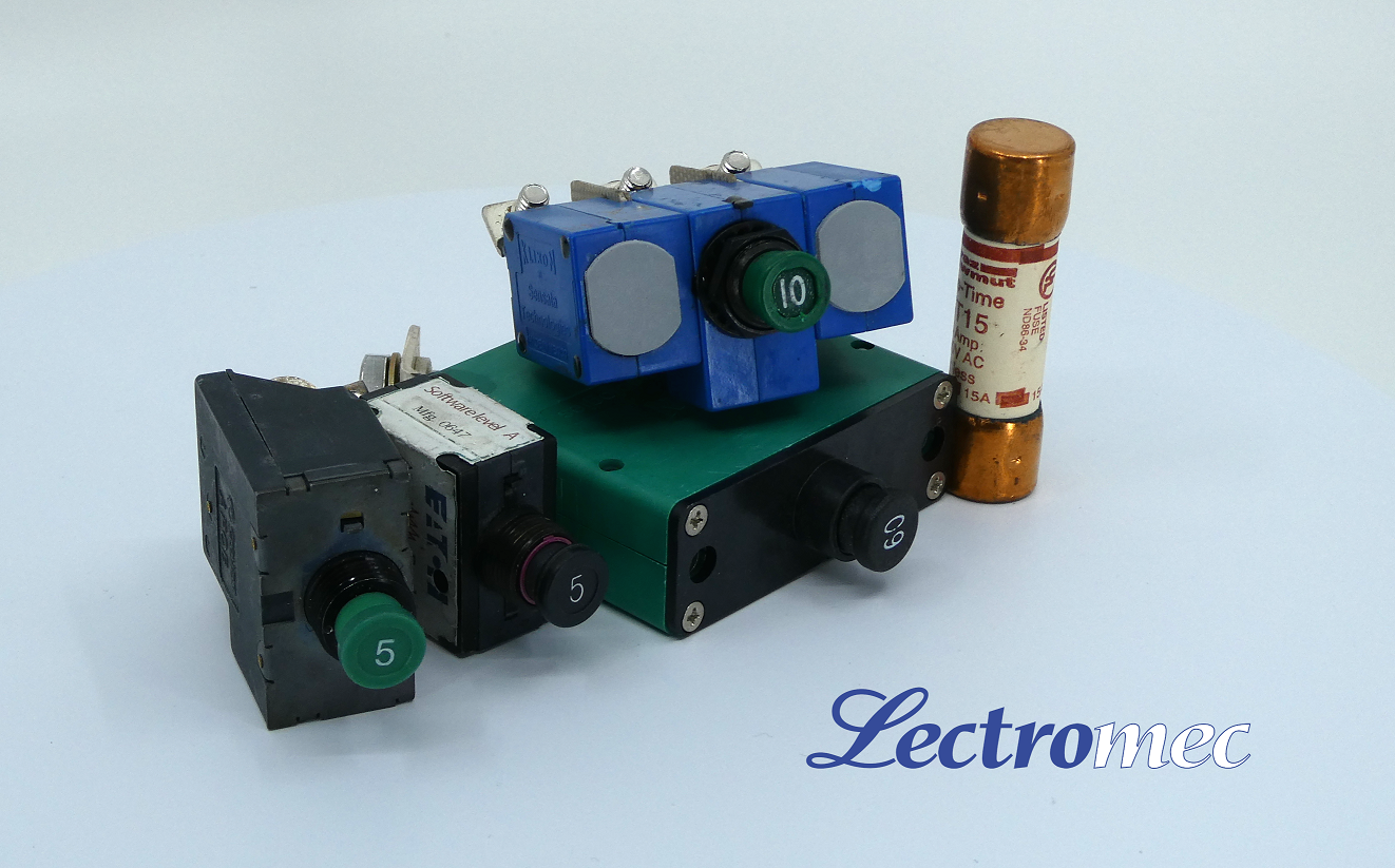
Some examples of circuit protection devices include circuit breakers (MS3320), arc fault circuit breakers (AS5692), fuses (AS5372A), and power distribution devices. These devices come in many shapes and sizes to suit the needs of a wide variety of electrical systems; naturally, aerospace applications push these devices to smaller and lighter packaging. A deeper discussion of the types of circuit protective devices can be found here
CFR 25.1717
FAA Regulation CFR 25.1717 covers circuit protection devices on aircraft and their relationship to the rest of the aircraft EWIS (Electrical Wiring Interconnection System). The requirement states:
“Electrical wires and cables must be designed and installed so they are compatible with the circuit protection devices required by § 25.1357, so that a fire or smoke hazard cannot be created under temporary or continuous fault conditions.”
A primary factor in meeting the requirement of this section is component selection – both of circuit protective devices and other EWIS components. The main considerations in component selection regarding circuit protection are type, rating, and compatibility.
Type – As mentioned above, circuit protective devices come in many shapes and sizes. Selecting the best type of circuit protection for a specific application requires evaluation of several system needs and limitations: size, weight, time to activation, circuit complexity, need to be reset during flight, and cost.
Rating – The selected circuit protection component(s) must be rated such that they are compatible with the current, voltage, and temperature requirements and limitations of the circuit they are applied to. Wire/ cable size, current-carrying capacity, and external heating factors are all crucial in determining the appropriate rating for selected circuit protection.
Compatibility – The selected means of circuit protection must be compatible with the rest of the circuit it is meant to protect. This becomes particularly interesting when modifications are made to the EWIS – compatibility must not be overlooked when modifying/ replacing components. For example, sizing a fuse for a motor to handle nominal loads may cause the fuse to trip during the surge current as part of motor startup.
Fire and Smoke
The CFR requirement for circuit protection explicitly calls for protection against smoke and fire hazards. Fault conditions are often accompanied by the potential occurrence of smoke or fire: excessive overheating of a wire may cause the insulation or support clamp to overheat and smoke; an electrical arc may ignite nearby flammable material. This is where the role of circuit protective devices becomes important.
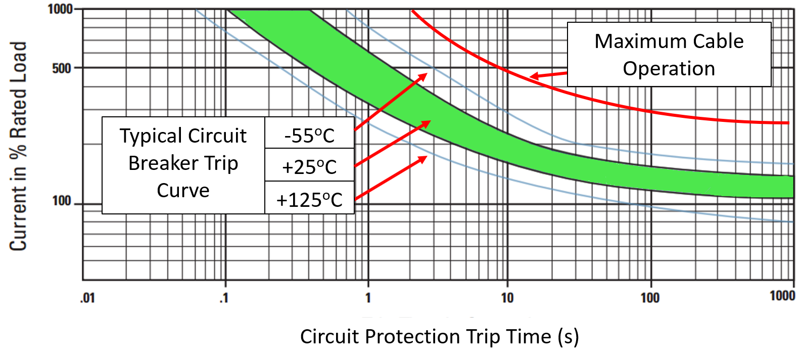
CFR 25.1717 requires that circuit protective devices prevent such events under fault conditions. Their purpose is to disconnect power to the circuit when hazardous conditions are detected – most frequently this is in the form of temperature or current exceeding a specified value. The incorporated circuit protection must activate with sufficient rapidity to prevent a fault from becoming a hazard. The rate at which a particular circuit protective device activates in a fault condition is typically represented in the form of a trip curve. These curves relate the time required for the circuit protection to trip to the current or temperature of the connected circuit component(s). More advanced circuit protection methods, such as those integrated into a distributed power controller, can be set to emulate a desired trip curve for more specialized protection.
Contributing Factors to Fault Conditions
There are many factors that influence the potential for a fault condition to occur.
- Overcurrent conditions
- Environmental/ external heating effects
- Electrical arcing
- Variable electrical load (most severe during takeoff and landing on most aircraft)
- Transient voltage spikes
- Aging of EWIS components
- Circuit protection device maintenance
- Loose or improper connections and terminations
Ideally, an aircraft electrical system will never experience a fault, this is, however, an unrealistic goal. Many of these factors are unavoidable regardless of how well the system is designed. For this reason, it is imperative that circuit protection components undergo tests representative of the system in which they are to be installed. Only with accurate representative data can an informed decision be made in selecting the appropriate components.
Electrical Arcing
One of the primary concerns in any electrical system is the potential for electrical arcing. Lectromec has published several articles (Link 1, Link 2, Link 3) on electrical arcing, so we will not go into too much detail here. As a brief explanation, electrical arcing occurs when electrical current ‘jumps’ from one conductive surface to another along an unintended path; this phenomenon can cause severe damage to EWIS and surrounding systems or even cause a fire in flammable environments.
Many circuit protective devices aim to mitigate the potential damage resulting from arcing events by disconnecting power to the circuit when a fault condition is detected but this task is not as straightforward as one may think. There are circuit protective devices, such as AFCBs (Arc Fault Circuit Breakers), that are designed specifically to reduce the duration of electrical arcs as they occur, but they are not compatible with every electrical circuit. Many circuits have electrical characteristics critical to their functions that may be interpreted by the breaker as arcing.
Thermal Circuit Breakers and Fuses
Arguably the most common circuit protective devices used in EWIS are thermal circuit breakers and fuses. Both components are lightweight, relatively inexpensive, historically reliable, and familiar to most of the people expected to interact with them making them very appealing options for circuit protection when designing EWIS. There are, however, a number of drawbacks to consider when selecting these components as they relate to CFR 25.1717.
Thermal circuit breakers are temperature sensitive (as the name implies); they are designed to trip when the temperature on the circuit reaches a specified maximum value. This functionality is very useful in preventing overcurrent and overheating faults, but one must consider external temperature factors. For instance, a thermal circuit breaker may not detect an overcurrent fault on a circuit as quickly if the system is operating in a very low temperature environment. By the time the circuit protection is activated, smoke or fire damage may already have occurred.
Additionally, thermal circuit breakers alone are not adequate for electrical arc protection. This leaves areas and equipment in potential arcing areas vulnerable to resulting smoke and fire.
Fuses are sensitive, one-time use components that essentially break apart an internal wire when overheating or overcurrent occur. Because of this, it is not possible to verify the appropriate performance of the individual component. Once it has tripped, the fuse needs to be entirely replaced – there is no means of determining whether the trip was caused by a faulty fuse or by a genuine circuit fault unless a full system assessment is performed.