Key Takeaways
- Current arc track resistance test methods are a cornerstone of aerospace wire/cable testing, but do not address the needs of newly developing high voltage systems.
- Considerations must be made as to whether arc track testing of the insulation should be performed on a completed wire construction or on the insulation material independently.
- Defining test voltage is non-trivial; a generic testing voltage for all systems may be defined, but the diversity of novel high voltage systems may require that testing be more system-specific.
Arc track resistance testing has been a staple of the aerospace industry for nearly 40 years. This originated from the issues raised in the 1980s with polyimide insulated wire. Since that time, test methods have evolved to assess and quantify the susceptibility of wires to carbon arc tracking and the ability to withstand electrical arcing events.
The test methods that exist today (such as in AS4373 and EN3475) address the needs of voltage systems up to 230VAC, but no further. Because of this, aircraft being designed with higher voltage power systems (those with voltages greater than 230VAC) do not have a clear industry-accepted approach to define the requirements of the electrical wiring interconnect system (EWIS) arc track resistance. While there is no clear solution on what direction the industry should take, this article explores the possible solutions and what they might mean for wire manufacturers and aircraft OEMs.
Starting with Materials
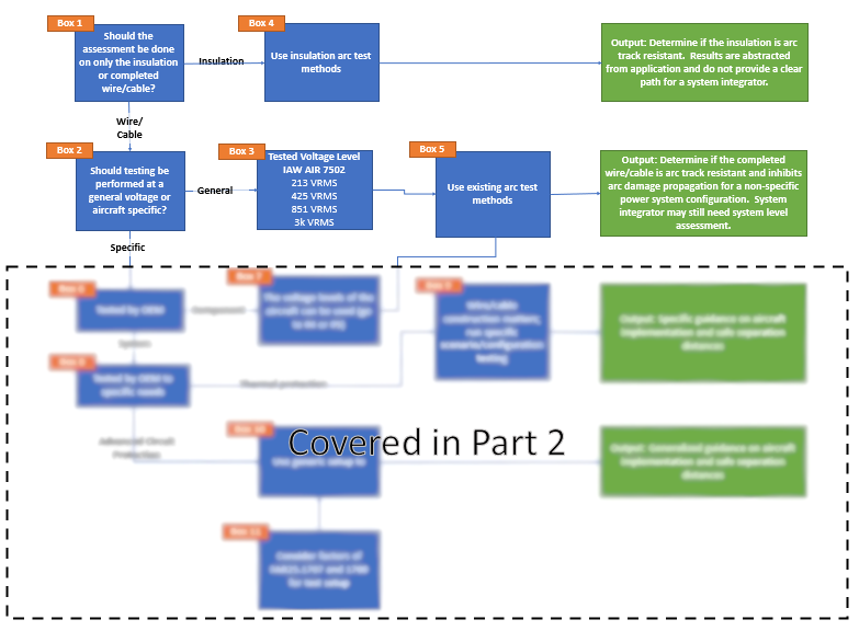
This flow chart demonstrates the logical flow in identifying arc track resistance considerations for high voltage systems. Additional considerations will be discussed in Part 2 of this discussion.
Note: To aid in the flow of possible solutions, please refer to the provided flow chart.
The first question to be asked is, “should arc track testing be performed on just the insulation or on a completed wire?” Suppose insulation materials are tested separately from the assembled wire/cable. In this case, alternative tests must be considered and an alternative means to quantify the insulation’s arc track performance should be established.
Insulation Testing
If alternative tests must be used (box 4), then how those test methods evaluate the materials must be considered. For example, consider the carbon tracking index test in accordance with ASTM 3638, the test method is only valid up to 600 VRMS. Further, any sort of composite construction, such as AS22759/187 (PTFE over polyimide), could never appropriately be tested because these tests are designed to test a single material, not multi-later composites. The ASTM D3638 test method calls for the testing of a single 10mm thick layer of the sample.
Other test methods like the ASTM D495 are tested with 15kV but again are appropriate only for single materials and not composite insulation constructions. The composite materials would then have to be tested separately and would likely yield different performance levels. This approach for composite constructions creates a challenge for defining the acceptable combined performance level for two (or more) material types.
As such, the standard material evaluation tests, unless they can account for composite material constructions, are not appropriate for wire insulation evaluations.
General Voltage Levels
If the testing should be done on a completed wire/cable, then, since the wires can potentially be used on a wide variety of power systems, the next question is, “Should the materials be tested at a single generic voltage, or should they be tested for the specific aircraft application?”.
If we say that they must be tested as specific voltage (box 3), then at what voltage should the wires/cables be tested? From an SAE perspective, that could be best defined by using the voltage thresholds identified in the AE7 standard AIR7502. The voltage used should then be at the maximum voltage from a given voltage level to ensure that it complies and is valid for all voltages under that threshold. Continuing down that thread, should the testing be done in accordance with standard dry and wet arc test methods? If done in accordance with existing test methods, the test is relatively straightforward: use the existing test methods with minor modifications (e.g., circuit protection with appropriate voltage rating) to address the specific voltage needs and move forward.
However, how these methods are used must also be considered. For those wire constructions that use the AS4373 test methods, there are usually three criteria to define pass/fail:
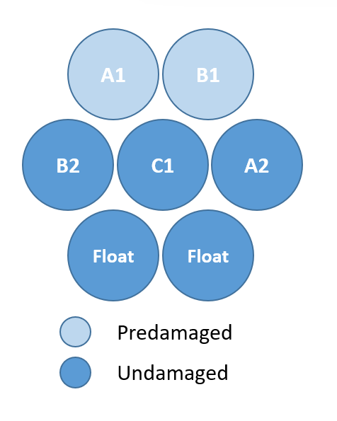
Cross-section diagram of an arc track resistance testing wire bundle in accordance with AS4373. Wires A1 and A2 are either pre-damaged (wet arc testing) or in direct contact with the abrading razor (dry arc) and are connected to the power source. Wires B2, C1, and A2 are not pre-damaged and are connected to the power source. The bottom two wires, the “passive wires” are not pre-damaged and are not connected to the power source.
- Only a very limited number of other wires in the test bundle may be significantly damaged to the point of insulation breach and still be acceptable,
- The total length of damage may not exceed 2 inches,
- Excluding wires A1 and B1, no more than three of the five other wires in a single bundle may be damaged.
The straightforward solution to meet these performance criteria would be to make the insulation thicker. This, unfortunately, contributes to design considerations such as weight, size, and wire/cable flexibility. Perhaps new materials may be able to address these needs without an insulation thickness penalty, but that remains to be seen.
Furthermore, if this approach is taken, what assumptions will be made for the testing and how much can a given power system vary from the tested power system and still be considered acceptable? For example, if a wire/cable is tested using an 850Vrms three-phase power system, how applicable are the results to a 1.2kVDC PWM power system? While a rational engineer could come up with reasonable assumptions, no research has yet been done to validate those assumptions.
Not Done Yet
Arc track resistance has been a required property of wires for decades, but unlike requirements such as conductor resistivity, the path forward for performance requirements is unclear. This article reviewed the factors for testing at the component manufacturing level (insulation producers and wire/cable fabricators), the next article focuses on questions aircraft OEMs will have to answer before fielding HV EWIS components.

Michael Traskos
President, Lectromec
michael.traskos@lectromec.comMichael has been involved in wire degradation and failure assessments for more than a decade. He has worked on dozens of projects assessing the reliability and qualification of EWIS components. Michael is an FAA DER with a delegated authority covering EWIS certification and the chairman of the SAE AE-8A EWIS installation committee.