View Latest Blog Entries
Close
Categories
Testing & Assessment Certification Standard & Regulation Aging Wires & Systems Maintenance & Sustainment Management Conference & Report Protection & Prevention Research Miscellaneous Arcing
Popular Tags
Visual Inspection High Voltage AS50881 MIL-HDBK MIL-HDBK-525 FAR AS4373 Maintenance Electromagnetic Interference (EMI) FAR 25.1707 Wire System Arcing Damage
All Tags in Alphabetical Order
2021 25.1701 25.1703 abrasion AC 33.4-3 AC 43 Accelerated Aging accessibility ADMT Aging Systems AIR6808 AIR7502 Aircraft Power System aircraft safety Aircraft Service Life Extension Program (SLEP) altitude arc damage Arc Damage Modeling Tool Arc Fault (AF) Arc Fault Circuit Breaker (AFCB) Arc Track Resistance Arcing Arcing Damage AS22759 AS22759/87 AS23053 AS29606 AS4373 AS4373 Method 704 AS50881 AS5692 AS6019 AS6324 AS81824 AS83519 AS85049 AS85485 AS85485 Wire Standard ASTM B355 ASTM B470 ASTM D150 ASTM D2671 ASTM D8355 ASTM D876 ASTM F2639 ASTM F2696 ASTM F2799 ASTM F3230 ASTM F3309 ATSRAC Attenuation Automated Wire Testing System (AWTS) Automotive Avionics backshell batteries bend radius Bent Pin Analysis Best of Lectromec Best Practice bonding Cable Cable Bend cable testing Carbon Nanotube (CNT) Certification cfr 25.1717 Chafing Chemical Testing Circuit Breaker circuit design Circuit Protection cleaning clearance Coaxial cable cold bend collision comparative analysis Compliance Component Selection Condition Based Maintenance Conductor Conductor Testing conductors conduit Connector Connector rating connector selection connector testing connectors contacts Corona Corrosion Corrosion Preventing Compound (CPC) corrosion prevention Cracking creepage D-sub data analysis data cables degradat Degradation Delamination Derating design safety development diagnostic Dielectric breakdown dielectric constant Dimensional Life disinfectant Distributed Power System DO-160 dry arc dynamic cut through E-CFR electric aircraft Electrical Aircraft Electrical Component Electrical Power Electrical Testing Electrified Vehicles Electromagnetic Interference (EMI) Electromagnetic Vulnerability (EMV) Electrostatic Discharge EMC EMF EN2235 EN3197 EN3475 EN6059 End of Service Life End of Year Energy Storage engines Environmental Environmental Cycling environmental stress ethernet eVTOL EWIS certification EWIS Component EWIS Design EWIS Failure EWIS sustainment EWIS Thermal Management EZAP FAA FAA AC 25.27 FAA AC 25.981-1C FAA Meeting failure conditions Failure Database Failure Modes and Effects Analysis (FMEA) FAQs FAR FAR 25.1703 FAR 25.1707 FAR 25.1709 Fault fault tree Fixturing Flammability fleet reliability Flex Testing fluid exposure Fluid Immersion Forced Hydrolysis fuel system fuel tank ignition Functional Hazard Assessment functional testing Fundamental Articles Fuse Future Tech galvanic corrosion Glycol Gold Gold plating Green Taxiing Grounding hand sanitizer handbook Harness Design harness protection hazard Hazard Analysis health monitoring heat shrink heat shrink tubing high current high Frequency high speed data cable High Voltage High Voltage Degradation HIRF History Hot Stamping Humidity Variation HV connector HV system ICAs IEC 60851 IEC60172 IEEE immersion insertion loss Inspection installation installation safety Instructions for Continued Airworthiness insulating material insulating tape Insulation insulation breakdown insulation resistance insulation testing interchangeability IPC-D-620 ISO 17025 Certified Lab ISO 9000 J1673 Kapton Laser Marking life limit life limited parts Life prediction life projection Lightning lightning protection liquid nitrogen lithium battery lunar Magnet wire maintainability Maintenance Maintenance costs Mandrel mean free path measurement mechanical stress Mechanical Testing MECSIP MIL-C-38999 MIL-C-85485 MIL-DTL-17 MIL-DTL-23053E MIL-DTL-3885G MIL-DTL-38999 MIL-E-25499 MIL-HDBK MIL-HDBK-1646 MIL-HDBK-217 MIL-HDBK-454 MIL-HDBK-516 MIL-HDBK-522 MIL-HDBK-525 MIL-HDBK-683 MIL-STD-1353 MIL-STD-1560 MIL-STD-1798 MIL-STD-464 MIL-T-7928 MIL-T-7928/5 MIL-T-81490 MIL-W-22759/87 MIL-W-5088 MIL–STD–5088 Military 5088 modeling moon MS3320 NASA NEMA27500 Nickel nickel plating No Fault Found OEM off gassing Outgassing Over current Overheating of Wire Harness Parallel Arcing part selection Partial Discharge partial discharge at altitude Performance physical hazard assessment Physical Testing polyamide polyimdie Polyimide-PTFE Power over Ethernet power system Power systems predictive maintenance Presentation Preventative Maintenance Program Probability of Failure Product Quality PTFE pull through Radiation Red Plague Corrosion Reduction of Hazardous Substances (RoHS) regulations relays Reliability Research Resistance Revision C Rewiring Project Risk Assessment S&T Meeting SAE SAE Committee Sanitizing Fluids Secondary Harness Protection separation Separation Requirements Series Arcing Service Life Extension Severe Wind and Moisture-Prone (SWAMP) Severity of Failure shelf life Shield Shielding Shrinkage signal signal cable Silver silver plated wire silver-plating skin depth skin effect Small aircraft smoke Solid State Circuit Breaker Space Certified Wires Splice standards Storage stored energy superconductor supportability Sustainment System Voltage Temperature Rating Temperature Variation Test methods Test Pricing Testing testing standard Thermal Circuit Breaker Thermal Endurance Thermal Index Thermal Runaway Thermal Shock Thermal Testing tin Tin plated conductors tin plating tin solder tin whiskering tin whiskers top 5 Transient Troubleshooting TWA800 UAVs UL94 USAF validation verification video Visual Inspection voltage voltage differential Voltage Tolerance volume resistivity vw-1 wet arc white paper whitelisting Winding wire Wire Ampacity Wire Bend Wire Certification Wire Comparison wire damage wire failure wire performance wire properties Wire System wire testing Wire Verification wiring components work unit code

Building Wire Harnesses Right

Management

Some of the most important elements to the electrical and electronic functions of aerospace vehicles are the cable and wiring harnesses. Accurate transmission of control and data signals is heavily dependent on the cable reliability, wiring harnesses, and connectors. Best design and maintenance practices are crucial to their longevity and reliability. Eliminating stresses to the wire and cable in the harness, as well as contamination in any electrical contact point is crucial to the effectiveness of a wiring harness system. The NASA technical standard, NASA-STD 8739.4, sets these “requirements for interconnecting cable and harness assemblies.” In this article, we review portions of the standard and what they mean for implementers.

Harnesses Layout and Fixturing

In advance of wire harness construction, it is common practice for mockups to be developed. According to the NASA technical standard, NASA-STD 8739.4, the mockup, commonly referred to as a ‘form board’, is used to account for all the physical restraints that are encountered by the cable or harness when installing on a platform. An example of a wiring harness layout. During the construction process, known as fixturing, harnesses are pre-formed, with bends and offsets, to fit a location. This occurs before the application of lacing tape, straps, shielding, or secondary protection, so the harness will not be under tension after installation.

aircraft wire
A formboard will typically be printed out, laid on a large board, pegs are placed on each side of the wire traces to guide the harness construction. This is an example diagram of harness formboard.

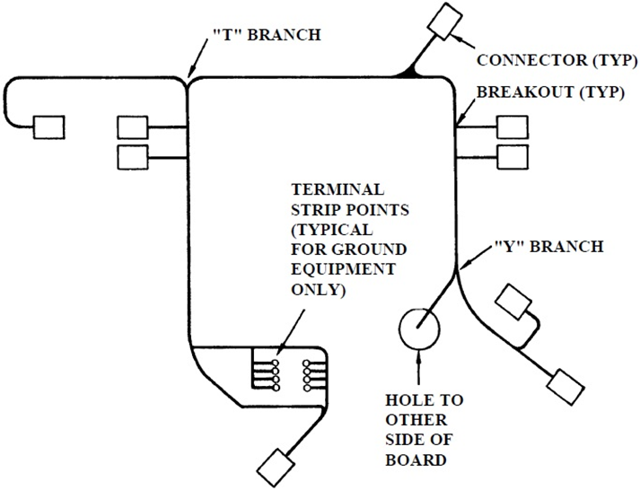
The form board layout should be designed to limit bending, pulling, and distortion during installation. The harness breakouts (locations in the harness where the wiring is split and goes two different directions) are secured on both sides using straps or lacing tape.

According to NASA’s Best Workmanship Practice, when coaxial or fiber optic cables are used in the wiring system, the harness should be designed to locate these cables near the center of the bundle to provide protection and limit bending. In practice, this can be difficult as wires and cables will shift during the harness construction/installation process.

There are limits on the flex or bending that a harness should undergo; is called its minimum bend radius. The harness bend radius varies based upon the size of the wires and the overall harness construction. Further, the inclusion of coaxial or fiber optic cables often will impact the bend radius of the harness and require a larger radius than if the harness only contained single wires or multicore cables.

Cable and Harness Protection

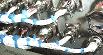
Secondary harness protection, or sleeving, is used for a variety of protective tasks. This protection material is used to protect from abrasion, chemical exposure, and heat/fire. Even though spacecraft wiring is not prone to operate in humid environments, moisture is still considered a contaminant and should be protected against. The NASA standard requires that the secondary harness protection sleeving to be installed on all terminations that are not potted. Typically, insulation sleeving is heat shrunk to provide a tight mechanical grip on the covered item as this provides an improved seal.

The NASA standard further recommends that when using pre-woven fabric braid, it must be loose enough to slide over the entire harness. The fabric sleeving is secured by straps, ties, clamps, heat-shrink, or potting material. When the braid is directly woven onto the harness, straps, ties, and “other temporary holding means” are removed prior to application, some “low profile” tapes may be left under the braid. Directly woven braids may be tightly applied to the harness or could be applied as loose as necessary to meet flexibility requirements.

aircraft wire
Implementing a clean wire system design is not a trivial task. The NASA standard provides good application recommendations.

EMI Protection

Another form of sleeving is metal braid. Although the metal braid offers mechanical protection to the harness, metal braid sleeving is typically used as EMI (Electromagnetic Interference) shielding. EMI is a major consideration when designing harnesses for sensitive equipment. It is a requirement, according to NASA technical standard, NASA-STD 8739.4, that harnesses are designed to minimize EMI between wires in the assembly.

Overall EMI shielding is the only type of sleeving that is not entirely insulated from the cable. To ensure the shield is at ground potential, the steel braid shielding is attached to the connector shell using RFI/EMI back shell adapters. The individual cable shield terminations are then electrically connected with the use of heat-shrinkable solder sleeves. To limit the potential impact of component failure, the recommendation is to limit the number of shields spliced to a common ground wire to no more than four. Lastly, excessive length of grounding wire may act as an antenna and should be trimmed.

Summary

The NASA standard provides good recommendations for designing and building wire harnesses for space applications. For those working on aircraft wire harnesses, this standard should be considered for areas within your own standard practices.

Further, it is sometimes necessary to get these external views into the design process to ensure every effort is taken for proper/reliable system design. The team at Lectromec is ready to help with the development or external review of your wiring practices. Contact us to find out more.

Alexander Petrov

Alexander Petrov

Engineer, Lectromec

Since starting at Lectromec in 2015, Alex has been key in many of test and assessment wire systems assessment projects wire systems assessment. His attention to detail has lead to several key insights in Lectromec’s research initiatives.