Updating Periodic Maintenance Procedures
An area of aircraft maintenance and wire system sustainment which has been around for the last decade is the enhanced zonal analysis procedures, or EZAP for short. EZAP is a set of procedures developed by the FAA during the 2000s detailing a systematic process for handling of wiring system maintenance based on zones.
Lectromec has covered EZAP multiple times in past articles (‘EZAP Basics’ and ‘EZAP and STC’). Each of these previous articles has covered different aspects of aircraft wiring maintenance as it relates to EZAP. In this article, we will develop an EZAP for an example aircraft zone. This example will consider the environmental factors and maintenance considerations as to how they impact the frequency and type of wire system inspections that should be performed.
For simplicity, the assessment shall focus on an easily accessible area of the aircraft, the wheel well.
Why is an EZAP necessary?
The first and most obvious reason: it is required by the FAA. Second: because this process defines the regular evaluation of all parts of the wiring system to aid the maintainers. The EZAP is done to reduce the risk from wire system failure. This is possible because the EZAP outputs should identify those areas that need regular inspection that can be integrated into existing A or B checks from those that are less at risk and can be evaluated at C or D check levels.
Maintenance Zone
One of the items that must be considered as part of the EZAP is the selection of the zone and where to place the boundaries. The most common recommendation is to align the zones with existing maintenance procedures and maintenance. This allows for easy integration into existing maintenance programs. While this was originally designed for part 25 aircraft, the EZAP can be just as applicable on smaller aircraft. Furthermore, this process was refined as part of the MECSIP recommendations for EWIS sustainment.
Environmental Conditions
Considering the wheel well, there are several environmental factors that immediately come to mind. The wheel well is not a pressure controlled environment and is subject to wide variations both in temperature and humidity. While the temperature swings are significant, the maximum temperature is not as severe as areas within close proximity of the engines. In terms of any other sort of chemicals or contamination that may be found within the wheel well zone, it is likely to be exposed to deicing fluids. Further, depending upon other types of systems running through this area, one might be able to expect contamination from other sources such as hydraulic fluids. For this example, we will assume this to be the case.
For our example zone, the wire harnesses are all protected by some form of secondary protection. The secondary protection is installed for the sake of protection from contamination, debris, and maintenance damage. This is an important risk mitigation factor that should be noted for this zone.
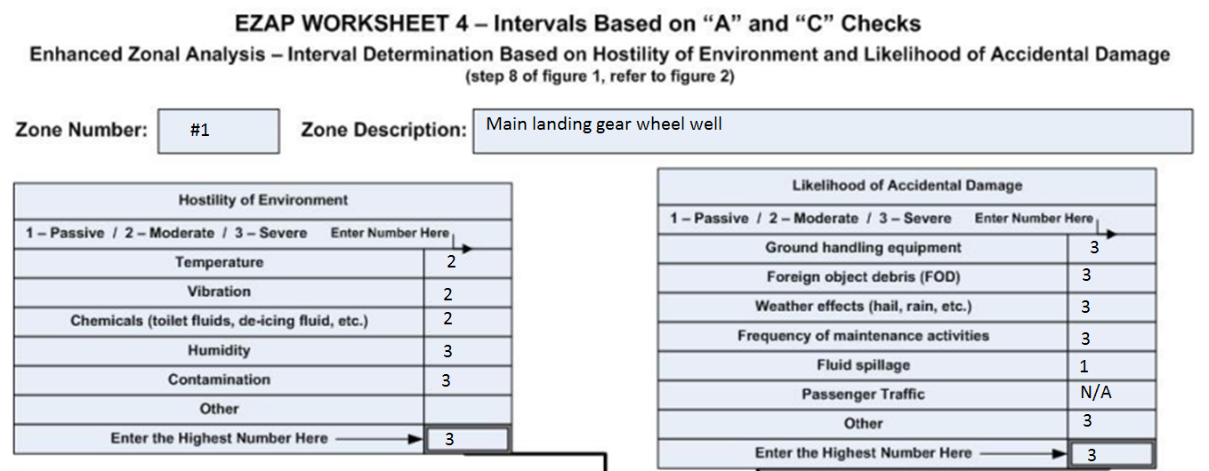
There are several more environmental factors that should be considered, however, that should be evaluated on a case-by-case basis per the advisory circular. The figure shown above is taken from the FAA advisory circular 25-27A. In the case of the wheel well example evaluated here, the potential environmental factors are included in the figure.
Zone Size
After all the environmental conditions have been evaluated it is important to consider the size and density of the zone. To identify what the size is from small, medium, or large, it is necessary to compare against other maintenance zones within the aircraft. Without a doubt a Boeing 787 will have a different definition of zone size than a part 23 aircraft so the size of the zone must be relative. For our example, we will consider the wheel well to be an average or medium-sized zone.
Density
Determining the zone density requires understanding of the zone itself. In order to understand this, the density of the installed equipment an evaluation including wires and other EWIS components should be performed. How to determine the level of congestion or density within the zone should be based off of how easy it would be to evaluate the wiring within the zone. An example used in the advisory circular is for the electronics compartment. This zone is often filled with a variety of Line Replaceable Units (LRUs) and it can be difficult to visually inspect all the wiring due to the congestion within the zone. For our example, while the wheel well is a medium-sized zone with a lot of the area taken up by the wheels, most of this area is open during inspections. As such, the density is considered to be low.
Fire
For the purposes of the EZAP, the impact of fire within a zone should be considered from the perspective of a fire that has occurred. This is where it becomes fully necessary to understand the routing of systems through the aircraft. Without knowledge of where systems are routed, it is impossible to identify what the impact of a fire might be. A zone that contains both primary and secondary flight controls has a very high severity of failure.
With that said, it is necessary to go through wiring diagrams and identify how different systems are routed through the aircraft. There are tools, like Lectromec’s EWIS risk assessment technologies, that can ease this process and help to rapidly identify the routing of systems through the aircraft.
For the purposes of our wheel well example, we will identify that the following systems are routed through this zone: communications, hydraulic power, landing gear, lights, and diagnostic/maintenance system. To determine the failure impact requires a thorough understanding of the risk mitigation designed into the aircraft and this can be a engineering labor intensive process. For our example, we will say that the engineering assessment determined that the loss of these would present a major but not catastrophic failure. The zone is given credit because there is fire suppression equipment, and thus the overall impact for the purposes of the evaluation is reduced.
Next Article
The EZAP process is a reliable method for evaluating the wire system on a regular basis. How this gets implemented is dependent upon the evaluator and the particular aircraft configuration. Integrating this into existing instructions for continued airworthiness does require knowledge of both. In the next article, we will continue with the EZAP process and how it can impact and integrate with existing maintenance procedures. For help or support in improving your existing wire system maintenance, contact Lectromec.