Key Takeaways
- A wire’s dielectric constant is related to the energy stored in the insulation.
- Lower insulation dielectric constants are preferred for high-speed data applications
- This parameter must be tightly controlled for impedance controlled systems.
A good wire insulation is more than just preventing electrical energy from leaving the conductor; there are dozens of properties that are important to its performance and usability. One of these that is easy to overlook is the wire’s dielectric constant.
From a conceptual viewpoint, a wire’s dielectric constant is usually thought of as a capacitor. Similar to a capacitor, the wire insulation can store energy. This energy storage capacity can be increased by choosing an insulating material with a higher dielectric constant.
But how does the dielectric constant play into electrical wire interconnection systems (EWIS)? The answer is that, in modern systems, it matters in several interesting ways.
What is Dielectric Constant
Dielectric constant (a.k.a relative permeability) is most easily understood in the context of a parallel plate capacitor. The formula for capacitance of parallel plate capacitor is the following: \(C = \epsilon D\frac{A}{d}\)
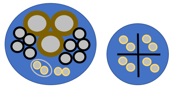
A wiring harness cross section [Left] and eight (8) wire cable [Right].
Where ‘ε’ is the permeability of free space (empty), ‘D’ is the dielectric constant, ‘A’ is the plate area and ‘d’ is the plate separation. This means a capacitor of given dimensions that has a capacitance ‘C0’ when there is a hard vacuum between the capacitor plates will have a capacitance of D * C0 when the insulating material (dielectric constant ‘D’) is inserted between the plates.
Air has a dielectric constant very close to that of a vacuum (empty space). Since material dielectric constants are greater than 1, inserting an insulating material increases the system’s capacitance.
Impedance of Capacitive Systems
When a sinusoidal signal is input into a system, the system’s impedance begins to have an impact on performance. Impedance of a purely capacitive system is given by the formula \(X=\frac{1}{2\pi fc}\) . This means that sinusoidal signals can be transmitted between system/components when there is capacitance between the components. The amount of transferred energy relates directly to the impedance between the components at the frequency of the signal source (it also relates to the power of the signal source). Low impedances will transfer more of the signal energy. Note that the impedance of the capacitive system decreases with increasing frequency and decreases with increasing capacitance.
As higher frequencies signals are used, the capacitive effects will increase due to the lower impedances at those frequencies. This also suggests that one way to limit this increase is by decreasing the capacitance between components. Decreasing capacitance can be done in several ways including:
- Decreasing the dielectric constant
- Increasing separation distances
- Decreasing the area of an electrode
Indeed, these are some of the strategies employed when considering Electromagnetic Interference (EMI) mitigation strategies and they specifically limit capacitive coupling as described above.
Relation to Noise and EMI Within Harnesses
Consider a typical wiring harness shown in first figure. Some of the wires may be power carrying wires, some of them may be low power signal wires. Some of the power from the power wire will transfer to the signal wire because of the capacitive impedance mentioned above. Since the power levels of the power carrying lines are much greater than on signal wire, and that hardware using signal wire will generally rely on low line level voltages, there is a real potential for noise (interference) on the signal circuits from the power lines.
One way to decrease the power transfer between wires would be to pick insulation and filler materials with low dielectric constants. This would decrease capacitance and increase the impedance between components. This is far from the only way to decrease power transfer, but it is one design choice that could lead to weight savings and a general decrease in power transfer between circuits.
The same thinking can be applied to capacitances within cables, however, in high frequency cable design, the characteristic impedance is another separate design consideration that is affected by changing the dielectric constant of cable materials. Changing the dielectric constant may be employed to, for example, decrease cross-talk within cables without increasing the volume or weight of the cable. Contact Lectromec if you would like cross-talk measurements made on your cable designs.
Relation to Cable Characteristic Impedance
The characteristic impedance of a cable will change depending on the dielectric constant of the materials used in cable construction. A model for an ideal transmission line is shown in the accompanying figure. Note that the capacitances in the model will be changed by such things as separation distance from inner conductor and shield (coax) or separation distance between the conductors of balanced twisted pairs. The capacitance will also be dependent on the dielectric constant of the insulating/filler materials used in cable construction. This will affect the characteristic impedance of the cable.
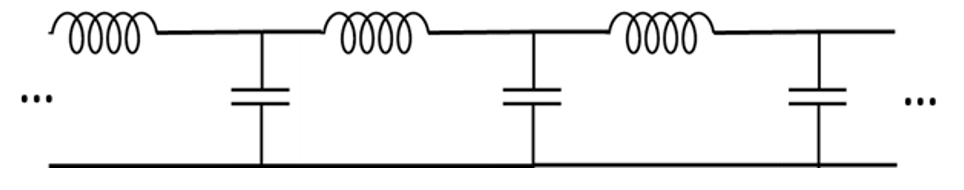
Ideal transmission line (coaxial cable).
Cables manufactured to specific characteristic impedances use materials with well-known dielectric constants. In high frequency circuits, impedance matching and controlled characteristic cable impedance is necessary to limit signal reflections. A fuller description of characteristic impedance and the need to control it is beyond the scope of this article and will be covered in future Lectromec articles.
Bringing it Together
The dielectric constant of a cable to is not just an interesting fact, but an important parameter than has an impact on the transmission of data. The dielectric constant factors into signal attenuation primarily limiting the performance at high frequencies.
Most wire/cable standards related to data/signal transmission test this parameter. It can be expected to see a progressive decrease in the dielectric constant as wire/cables continue to evolve for those critical, high-speed applications.

Tristan Epp Schmidt
Engineer, Lectromec
info@lectromec.comSince starting at Lectromec in early 2015, Tristan has been key in many of test and assessment wire systems assessment projects wire systems assessment. His attention to detail has lead to several key insights in Lectromec’s research initiatives.