Key Takeaways
- Condition Based Maintenance plus (CBM+) is the latest initiative seeking to get ahead of maintenance issues with data.
- There are a several means for performing risk assessments.
- Lectromec is holding a live webinar July 20th on “Integrating EWIS into MECSIP”.
Aircraft maintenance is usually broken down one of two ways: by physical zones or by systems. The mechanical equipment and subsystems integrity program, also known as MECSIP, is the US Air Force’s approach to addressing aircraft sustainment and maintenance through focused system evaluation. Last week, MECSIP managers from many of the Air Force fleets gathered in Dayton, Ohio to discuss the latest developments, procedures, and technologies for addressing the MECSIP needs of their fleets.
Lectromec had the opportunity to attend and present to this committee. This article covers some of the presentations given during this meeting. If you are interested to find out more about Lectromec’s presentation, we will be hosting a webinar in July. Click here for details and to sign up.
Condition-Based Maintenance
A topic of discussion at the MECSIP meeting was the idea of condition-based maintenance (CBM). The program initiative, working under the acronym CBM+, seeks to get ahead of maintenance issues by using data gathered by the maintainers, specifically the technicians with the most regular interaction with the aircraft.
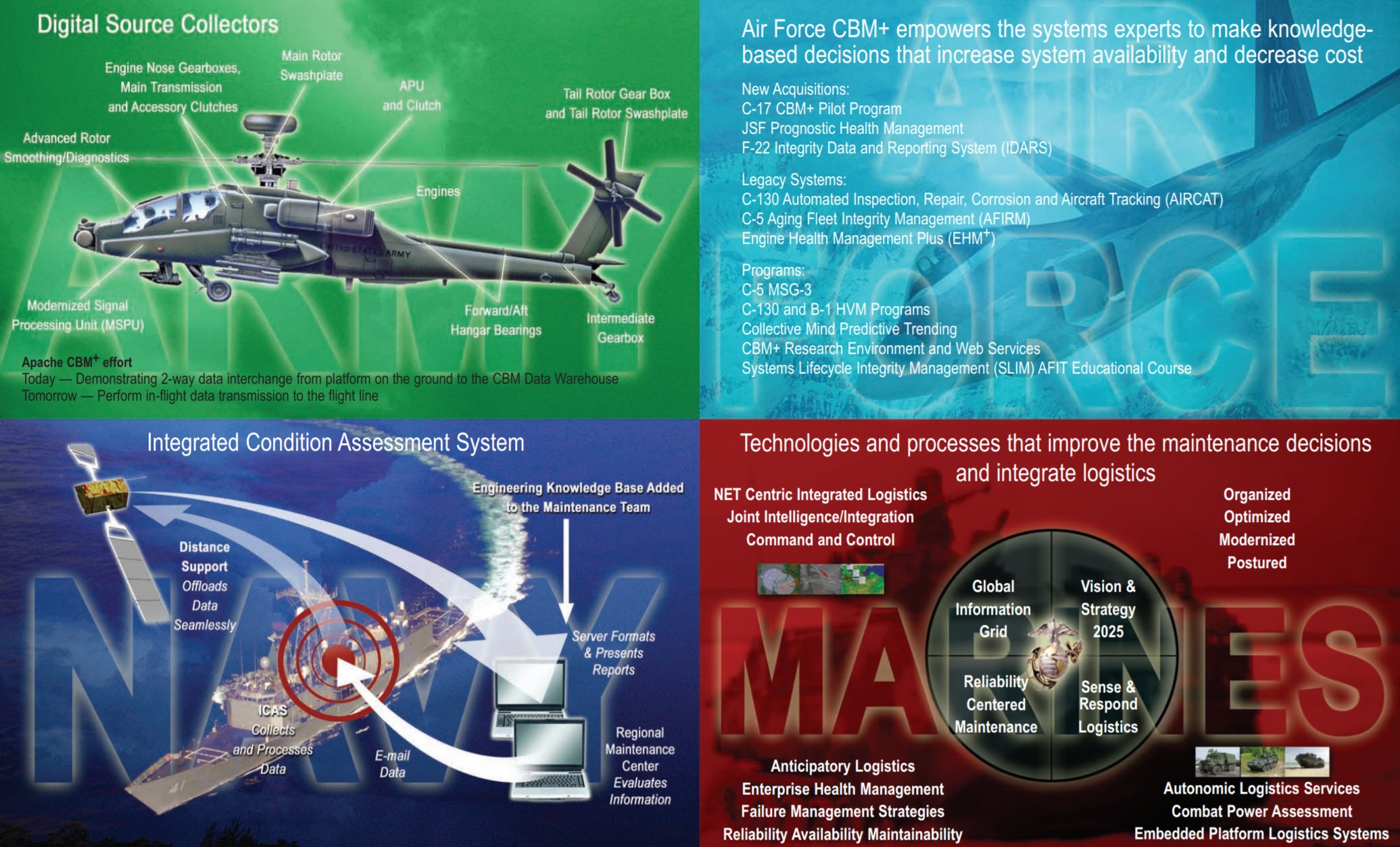
An overview of CBM+. Source DoD.
Engineers always want more data, but the systems and procedures for maintaining the USAF aircraft make it difficult for the aircraft technicians to record the data. The CBM+ initiative objective is to find ways to gather more data without placing an additional burden on the aircraft maintainer. They recognize the fact that any task that will increase the maintainer’s workload will likely be met with resistance and not be implemented.
At the fundamental level, the CBM+ seeks to get ahead of issues by trying to remove the concept of flying to failure (the idea that a component should remain on the aircraft until it has failed). To avoid the fly to failure scenarios, accurate part data reflecting its usage and service history are necessary.
The USAF CBM+ group has learned from recent maintenance successes of the Delta Airline Tech Ops team. To avoid costly downtime of their aircraft, Delta has started to place spare equipment on their aircraft that they believe is near failure. Doing so allows for rapid replacement of worn parts wherever the aircraft is located. While the Delta implementation may not be practical for all Air Force fleets, the concept of having readily available spare parts based on remaining health is a novel idea.
Certainly, the complications of gathering such health information, logistics, and a host of other sustainment issues require a lot of coordination and planning before they can be implemented. But if they can be properly implemented, there will be a significant performance improvement across the fleet.
Risk Assessment
One of the challenges associated with aircraft sustainment and maintenance is to quantify the risk to the aircraft and then take the necessary actions to ensure airworthiness. Because of the complexity and the breath of risk assessment across multiple fields/industries, there are dozens of ways to approach a risk assessment. One of the issues for military maintainers is the variety of risk assessment metrics and techniques in aircraft standards.
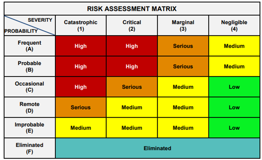
The field of risk assessment is still evolving. This table is the latest guidance from MIL-STD-882 (rev E).
Perhaps the document most cited for aircraft system safety is MIL-STD-882E, simply titled “system safety”. This document outlines specific means of quantifying risk across multiple systems. For anyone that has been part of the industry for more than a couple years has certainly seen some representation of the risk assessment matrix figure (MIL-STD-882 table 3)
From an Air Force perspective, the method for quantifying risk has created some issues. In particular, there is uncertainty if the risk should be reported on the individual aircraft level or across the fleet. For example: The F-16 fleet has over 1000 aircraft and if a direct comparison were to be made of any component failing on the fleet versus a similar component on a smaller fleet, such as the B1s, the comparison would look something like this:
Where:
- CFP is the component failure rate
- FHPY is the flight hours per year
- NumAC is the number of aircraft in the fleet
The failure rate of the F-16 fleet would appear to be at least an order of magnitude greater. But at the individual aircraft level, the failure probability remains the same. As such, the current guidance is for the risk to be considered on the basis of the individual aircraft to allow for a more comparable risk to be quantified.
One thing also highlighted at the MECSIP managers meeting was there are very few factors with an aircraft that have a constant failure rate. While things like lightning strike and bird strike are consistent over the life of the aircraft, all components in the aircraft degrade over time. It is simply the component’s use and care that create the performance variability.
Without a doubt, Lectromec has been talking about EWIS degradation for nearly four decades. A quick search of Lectromec’s website will find dozens of articles highlighting different EWIS component degradation mechanisms. The bathtub curve of component failure rates holds true across the board.
The last item to be touched upon here is to highlight the difference between three risk assessment terms. The first is risk. Risk is the combination of failure probability and failure severity; Table 3 shown earlier shows the qualitative combination of these two factors.
The term Risk Impact describes the effect of total severity of a hazard for a specific exposure. For example, was the risk over a given year? This helps to provide a time-based focus on component or system degradation in a means by which different systems/platforms can be compared.
Lastly the term Aggregate Risk describes the collected risk of all aircraft related hazards. For those familiar with fault trees, this would be the summation of all top-level fault tree events.
A greater level discussion about risk, is qualification, and if limitation is described in Air Force policy memo 91-202.
More to Come
The three-day MECSIP managers meeting cannot be collapsed into a single article as a large number of topics covered should be considered when working with or maintaining aircraft. However, what should be highlighted here is that those which are responsible for maintaining these vehicles are looking across the board for solutions to address risk, better quantify an aircraft’s condition, and get the actionable information to make educated predictive maintenance decisions.
Lectromec also presented at this conference specifically on lessons learned from past EWIS evaluations and what those lessons learned mean to MECSIP. Next month, Lectromec will host a live webinar covering many of these topics. We will have more details to come but if you are interested in receiving information about this webinar click the following link.

Michael Traskos
President, Lectromec
michael.traskos@lectromec.comMichael has been involved in wire degradation and failure assessments for more than a decade. He has worked on dozens of projects assessing the reliability and qualification of EWIS components. Michael is an FAA DER with a delegated authority covering EWIS certification and the chairman of the SAE AE-8A EWIS installation committee.