Key Takeaways
- Corrosion of silver plated copper conductors and shields has been an issue for decades.
- There are separate test methods that are appropriate at different stages of a wire/cable’s life cycle.
- Several test methods are proposed and dependent on where the wire/cable is in the production process.
Lectromec has covered red plague testing, and the developments surrounding it, for the last 15 years. For information on the progress and developments of red plague testing and the fundamentals behind it, please see these articles.
This article dives into the practical applications of red plague testing and how to identify and potentially mitigate the risks thereof. The other articles Lectromec has published up to this point have been single test focused or focused on the fundamentals. This article gives a guide to those seeking means to quantify the risk of red plague on their components.
Short Introduction
In short, red plague is corrosive galvanic corrosion that occurs between the silver plating and copper core of silver-plated copper wire. This has been a known issue since at least the 1950s and has popped up dozens of times since then with issues identified during initial product inspection, at product acceptance, as well as cases where red plague corroded wires and cables resulted in multi-million dollar rewiring efforts.
At different stages of production, different tools and assessment techniques must be used to determine the susceptibility of a conductor or shield to the red plague. The following gives a step-by-step about what techniques are viable at different parts of the production process.
Bare Conductor
Has the conductor been processed or stranded? If no, then the recommended means of assessment is the polysulfide test in accordance with ASTM B298. In this test, the bare conductor is exposed to a polysulfide solution that will have a chemical reaction with any exposed copper. This exposed copper looks tarnished and blackened and easy to observe by visual inspection or by handheld magnification. The reason that this test is recommended at the early stages of the process is that silver is a malleable material and can be easily damaged during stranding or processing. As such, it is extremely common that a conductor that has been stranded and processed will show some level of tarnishing during the polysulfide test. Further, the conductors used for shielding are stressed and commonly show a failure in the polysulfide test. If the conductor is already stranded or added to a cable shield, then alternate test methods are suggested that are discussed below.

Process for assessing the red plague susceptibility of conductors, wires, cables, and/or shielded harnesses.
Insulation or jacket performance
Are you aware of the jacket or insulation fluorine off gassing properties? If you are unaware of how wire insulation contributes to the progression of red plague, we recommend that you review this article. In short, some wire insulations have a higher proclivity to off-gas fluorine which is a critical factor in red plague development. As such the industry has developed wire and jacket insulations that are known as “low fluorine off-gassing” systems. To assess the off-gassing propensity of the jacket or wire insulation, Lectromec recommends the use of the AS4373 test method 608. This test is a 1-week test in which the installation or jacket is submerged in water and the extractive fluorine is measured afterward. Research has found that values below 20 ppm of extractable fluorine do not yield red plague.
Completed Harness Susceptibility
Right now, there is no formal mechanism to assess the susceptibility of a completed harness to red plague. The test methods that exist, focus on the examination at the conductor, insulation, or completed wire level. To assess the red plague susceptibility of a completed harness requires a slight modification of AS4373 method 610. In this test method, it is intended that sections of a completed wire or cable are submerged in water but with a copper and silver electrode also submerged into the solution. The voltage drop between the two electrodes is monitored for 14 days and the voltage over that fortnight is examined. If the collected voltage across the 14 days has a specific shape, in particular, an inflection point of the voltage before day four, then it is considered highly susceptible to red plague. As mentioned, this test method is originally designed for individual wires and cables but could just as easily be applied to a completed section of the harness. This would allow for assessing the susceptibility of the completed harness as well as the examination of any silver plated metallic overbraid for the harness.
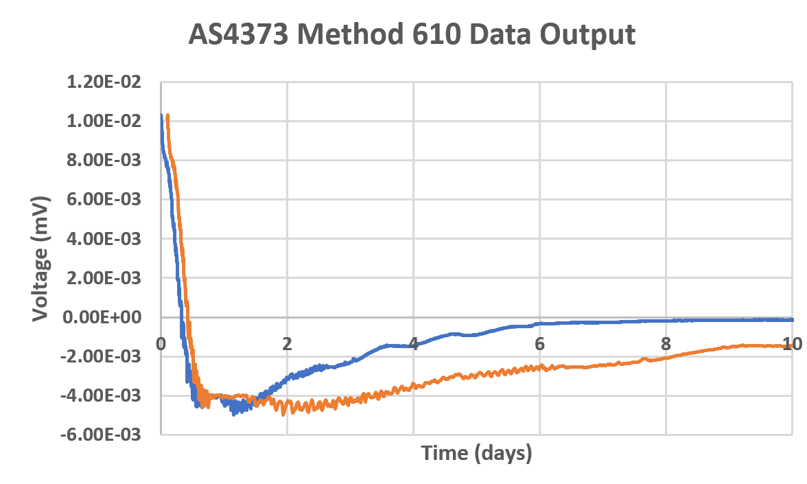
This chart shows the testing of two samples. The blue line represents one sample highly susceptible to red plague as indicated by the inflection point in the voltage before day 4. The orange line represents a sample susceptible to red plague, but in an application, it would take some time before red plague would appear.
For those seeking assessment of the red plague susceptibility of their wires, cable, or wire harness, the proposed means of assessment have been identified. Research at this point has primarily focused on red plague susceptibility at the wire and cable level and there is an opportunity for additional research on the red plague susceptibility at the wire harness level. The development of a test plan around this would involve using both normal cross-linked ETFE wire insulation as well as low fluorine off-gassing wire insulation on shielded harnesses and examining the performance difference when tested in accordance with method AS 4373 method 610.
How to Move Forward
For those seeking support or testing to determine the red plague susceptibility of your components, contact Lectromec. We have been assessing red plague susceptibility for a decade and can help you assess and quantify the risk of red plague with your components and/or your project.

Michael Traskos
President, Lectromec
michael.traskos@lectromec.comMichael has been involved in wire degradation and failure assessments for more than a decade. He has worked on dozens of projects assessing the reliability and qualification of EWIS components. Michael is an FAA DER with a delegated authority covering EWIS certification and the chairman of the SAE AE-8A EWIS installation committee.