Insertion Loss and Attenuation
Every industry and every field have their unique definitions, acronyms, and shorthand. While it is not the intention of the developers of these terms, the fact is that the unique vernacular acts as a barrier to entry for many who seek to learn more and understand. To that end, while ‘insertion loss’ and ‘attenuation’ sound very similar (and in many ways are similar), there are subtle differences that exist and are covered in this article.
Attenuation
Signal attenuation is simply the reduction in signal strength as it travels along the cable. To put this another way, any real conductor possesses an inherent electrical resistance. As a result of this resistance, the transmitted signal weakens as it travels along the cable resulting in a lower voltage signal at the receiver than was initiated at the transmitter. The attenuation is the ratio between the strength of these signals.
Several factors impact a cable's attenuation:
- Frequency: Higher frequencies will experience more attenuation than lower frequencies. This is because higher frequency signals encounter more resistance (see skin effect article) and dielectric losses as they travel through the cable.
- Cable Length: Longer cables exhibit greater attenuation experiencing more resistance and losses from end to end. Typically though, the attenuation per unit length will be relatively constant.
- Conductor Type/Plating: The conductor material and plating influence its attenuation characteristics. More conductive materials such silver plated copper conductors will have lower attenuation compared to aluminum conductor cables.
- Conductor Size: Larger conductors will have lower attenuation as they offer lower resistance to the flow of electrical signals.
- Dielectric Constant: The dielectric constant of the insulating material surrounding the core conductor affects attenuation. Lower dielectric constant materials (such as PTFE) reduce attenuation by minimizing the capacitance between the conductors; in the case of coax cables, this dielectric material is between the core conductor and the shield.
- Temperature: Temperature variations can affect the attenuation of a cable. Higher temperatures can increase resistance within the cable, leading to higher attenuation. Depending on the material type used, the insulating material’s dielectric constant may change because of higher or lower operational temperatures.
- Shielding: The quality, coverage, and plating of the cable shielding will impact attenuation.
- Installation Conditions: The cable installation conditions, such as bending, twisting, or crushing under clamps, can affect its attenuation characteristics. Improper installation can introduce additional losses. Guidance documents like AS50881 provide a basis for best installation practices.
Insertion Loss
Insertion loss refers to the cumulative impact that the factors above have on reducing the signal strength or power when a device or component is inserted into a communication system or transmission line. The insertion loss is typically measured in decibels (dB) and represents the amount of signal power lost as it passes through the device. Insertion Loss can be measured across several components or by each connector, splice, switch, or any other component through which the signal passes. The insertion loss is usually specified by component manufacturers, and it is essential to minimize it to ensure efficient signal transmission and system performance.
Minimizing insertion loss is important to ensure that the transmitted signals remain strong and undistorted throughout the communication system. Engineers and designers carefully select cables and connectors based on their insertion loss characteristics to meet the requirements of specific applications.
Differences Between Attenuation and Insertion Loss
Attenuation and insertion loss are closely related concepts that are meant to quantify the signal strength reduction in communication systems, but they are used in different contexts and have distinct meanings:
- Attenuation:
- Definition: Signal attenuation refers to the overall reduction in the magnitude or intensity of a signal as it travels through a medium, such as a cable or transmission line. Another way to put it is that attenuation is to signal applications, as voltage drop is to power applications.
- Scope: Attenuation is a broader term that encompasses all factors contributing to signal loss, including factors like absorption, scattering, and reflection.
- Units: Attenuation is typically measured in decibels (dB) and can be expressed as a ratio of output power to input power. Often for signal cables, the attenuation is expressed in loss per length (e.g., dB/100ft).
- Insertion Loss:
- Definition: Insertion loss specifically refers to the loss of signal strength that occurs when a device or component is inserted into a transmission line or communication system. It is the decrease in power caused by the introduction of a component like a cable, connector, or a completed connectorized harness.
- Scope: Insertion loss focuses on the impact of a specific component on the signal strength, and it is often used to describe the performance of connectors, cables, or other devices within a system.
- Units: Insertion loss is measured in decibel milliwatts (dBm), quantifying the reduction in signal power.
In summary, attenuation is a general term describing the overall reduction of a signal's magnitude as it propagates through a medium, while insertion loss specifically refers to the reduction in signal strength caused by the insertion of a particular component into the system. Insertion loss is a subset of attenuation, and when discussing the performance of specific components in a communication system, insertion loss is a more focused and relevant metric. For generalized cable performance, attenuation is the comparative metric that should be used.
Test Methods
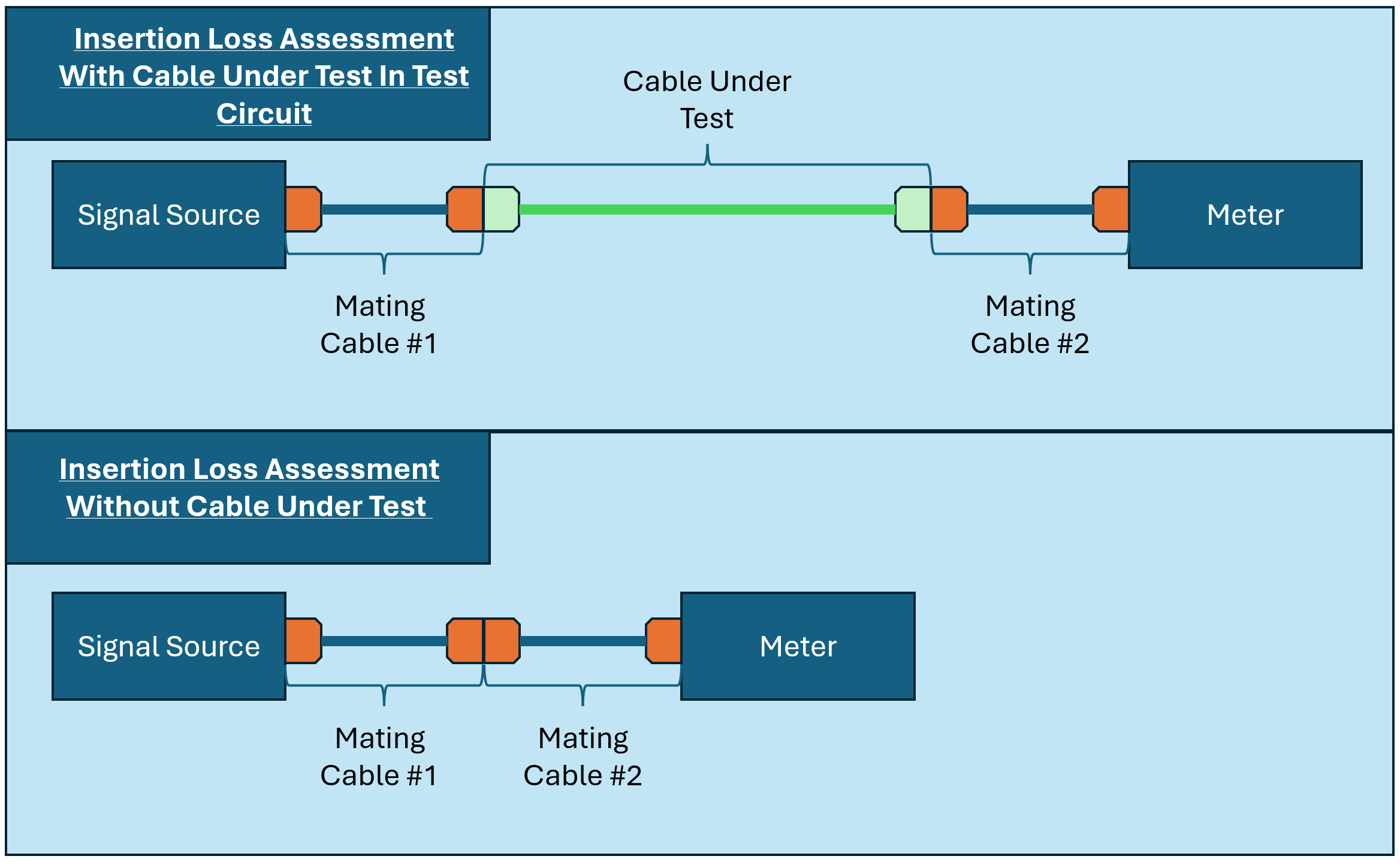
Insertion loss measurement methods for coaxial cable vary slightly in terms of execution, but all remain fundamentally similar. Two circuits are constructed; these circuits should be as similar as possible, except that one circuit includes the CUT (Cable Under Test) and the other does not. The second circuit may require an additional coupler or jumper cable to complete the circuit and these new parts need to be separately evaluated to determine their insertion loss. The circuits are then tested with a power meter and signal source and the change in power level is reported as the component’s insertion loss. This test may be performed at a single frequency or across a wide frequency spectrum.
The choice of the specific test method depends on factors such as the application requirements, the frequency range of interest, and the available testing equipment. Often, a combination of methods may be used for a comprehensive assessment of insertion loss in coaxial cables.
Test Standards for Coaxial Cables
Several standards are commonly used for testing insertion loss in coaxial cables. The choice of a specific standard may depend on the application, frequency range, and industry requirements. Here are some notable standards relevant to the testing of insertion loss in coaxial cables:
- IEC 61196
- MIL-DTL-17
- MIL-PRF-39012
- MIL-PRF-55339
- MIL-T-81490
When testing insertion loss in coaxial cables, it's essential to refer to the specific standards relevant to the application and type of cable being used. These standards often detail the testing procedures, equipment requirements, and performance criteria necessary to ensure compliance and reliable cable performance.
Conclusion
Insertion loss and attenuation are similar concepts, but one is assigned to a single component (insertion loss) whereas the other is assigned to generalized performance (attenuation). Early in design, it is likely that a cable’s attenuation performance will take priority; as the system evolves and specific distances and requirements emerge, insertion loss becomes the dominant performance requirement. The mechanisms for measuring each are similar and, like all testing, care must be taken to ensure that the testing is done right and applies to the application. To find out more about signal cable testing, contact Lectromec. Our ISO 17025 accredited lab is ready to help.