View Latest Blog Entries
Close
Categories
Testing & Assessment Certification Standard & Regulation Aging Wires & Systems Maintenance & Sustainment Management Conference & Report Protection & Prevention Research Miscellaneous Arcing
Popular Tags
Visual Inspection High Voltage AS50881 MIL-HDBK MIL-HDBK-525 FAR AS4373 Electromagnetic Interference (EMI) Maintenance FAR 25.1707 Wire System Arcing Damage
All Tags in Alphabetical Order
2021 25.1701 25.1703 abrasion AC 33.4-3 AC 43 Accelerated Aging ADMT Aging Systems AIR6808 AIR7502 Aircraft Power System aircraft safety Aircraft Service Life Extension Program (SLEP) altitude arc damage Arc Damage Modeling Tool Arc Fault (AF) Arc Fault Circuit Breaker (AFCB) Arc Track Resistance Arcing Arcing Damage AS22759 AS22759/87 AS23053 AS29606 AS4373 AS4373 Method 704 AS50881 AS5692 AS6019 AS6324 AS81824 AS83519 AS85049 AS85485 AS85485 Wire Standard ASTM B355 ASTM B470 ASTM D150 ASTM D2671 ASTM D8355 ASTM D876 ASTM F2639 ASTM F2696 ASTM F2799 ASTM F3230 ASTM F3309 ATSRAC Attenuation Automated Wire Testing System (AWTS) Automotive Avionics backshell batteries bend radius Bent Pin Analysis Best of Lectromec Best Practice bonding Cable Cable Bend cable testing Carbon Nanotube (CNT) Certification cfr 25.1717 Chafing Chemical Testing Circuit Breaker circuit design Circuit Protection cleaning clearance Coaxial cable cold bend collision comparative analysis Compliance Component Selection Condition Based Maintenance Conductor Conductor Testing conductors conduit Connector Connector rating connector selection connector testing connectors contacts Corona Corrosion Corrosion Preventing Compound (CPC) corrosion prevention Cracking creepage D-sub data analysis data cables degradat Degradation Delamination Derating design safety development diagnostic Dielectric breakdown dielectric constant Dimensional Life disinfectant Distributed Power System DO-160 dry arc dynamic cut through E-CFR electric aircraft Electrical Aircraft Electrical Component Electrical Power Electrical Testing Electrified Vehicles Electromagnetic Interference (EMI) Electromagnetic Vulnerability (EMV) Electrostatic Discharge EMC EMF EN2235 EN3197 EN3475 EN6059 End of Service Life End of Year Energy Storage engines Environmental Environmental Cycling environmental stress ethernet eVTOL EWIS certification EWIS Component EWIS Design EWIS Failure EWIS sustainment EWIS Thermal Management EZAP FAA FAA AC 25.27 FAA AC 25.981-1C FAA Meeting failure conditions Failure Database Failure Modes and Effects Analysis (FMEA) FAQs FAR FAR 25.1703 FAR 25.1707 FAR 25.1709 Fault fault tree Fixturing Flammability fleet reliability Flex Testing fluid exposure Fluid Immersion Forced Hydrolysis fuel system fuel tank ignition Functional Hazard Assessment functional testing Fundamental Articles Fuse Future Tech galvanic corrosion Glycol Gold Gold plating Green Taxiing Grounding hand sanitizer handbook Harness Design harness protection hazard Hazard Analysis health monitoring heat shrink heat shrink tubing high current high Frequency high speed data cable High Voltage High Voltage Degradation HIRF History Hot Stamping Humidity Variation HV connector HV system ICAs IEC 60851 IEC60172 IEEE immersion insertion loss Inspection installation installation safety Instructions for Continued Airworthiness insulating material insulating tape Insulation insulation breakdown insulation resistance insulation testing interchangeability IPC-D-620 ISO 17025 Certified Lab ISO 9000 J1673 Kapton Laser Marking life limit life limited parts Life prediction life projection Lightning lightning protection liquid nitrogen lithium battery lunar Magnet wire maintainability Maintenance Maintenance costs Mandrel mean free path measurement mechanical stress Mechanical Testing MECSIP MIL-C-38999 MIL-C-85485 MIL-DTL-17 MIL-DTL-23053E MIL-DTL-3885G MIL-DTL-38999 MIL-E-25499 MIL-HDBK MIL-HDBK-1646 MIL-HDBK-217 MIL-HDBK-454 MIL-HDBK-516 MIL-HDBK-522 MIL-HDBK-525 MIL-HDBK-683 MIL-STD-1353 MIL-STD-1560 MIL-STD-1798 MIL-STD-464 MIL-T-7928 MIL-T-7928/5 MIL-T-81490 MIL-W-22759/87 MIL-W-5088 MIL–STD–5088 Military 5088 modeling moon MS3320 NASA NEMA27500 Nickel nickel plating No Fault Found OEM off gassing Outgassing Over current Overheating of Wire Harness Parallel Arcing part selection Partial Discharge partial discharge at altitude Performance physical hazard assessment Physical Testing polyamide polyimdie Polyimide-PTFE Power over Ethernet power system Power systems predictive maintenance Presentation Preventative Maintenance Program Probability of Failure Product Quality PTFE pull through Radiation Red Plague Corrosion Reduction of Hazardous Substances (RoHS) regulations relays Reliability Research Resistance Revision C Rewiring Project Risk Assessment S&T Meeting SAE SAE Committee Sanitizing Fluids Secondary Harness Protection separation Separation Requirements Series Arcing Service Life Extension Severe Wind and Moisture-Prone (SWAMP) Severity of Failure shelf life Shield Shielding Shrinkage signal signal cable Silver silver plated wire silver-plating skin depth skin effect Small aircraft smoke Solid State Circuit Breaker Space Certified Wires Splice standards Storage stored energy superconductor supportability Sustainment System Voltage Temperature Rating Temperature Variation Test methods Test Pricing Testing testing standard Thermal Circuit Breaker Thermal Endurance Thermal Index Thermal Runaway Thermal Shock Thermal Testing tin Tin plated conductors tin plating tin solder tin whiskering tin whiskers top 5 Transient Troubleshooting TWA800 UAVs UL94 USAF validation verification video Visual Inspection voltage voltage differential Voltage Tolerance volume resistivity vw-1 wet arc white paper whitelisting Winding wire Wire Ampacity Wire Bend Wire Certification Wire Comparison wire damage wire failure wire performance wire properties Wire System wire testing Wire Verification wiring components work unit code

In Lectromec’s previous article, we introduced a basis for estimating connector failure rates. The framework utilized the failure information available from military handbook MIL-HDBK-217. In this article, we continue to review the parameters of the failure rate function and implications on how slight changes in the environment can have a dramatic impact on a connectors reliability.

Operational Temperature Impact

As established in the previous article, different connector types are assigned different failure rates. Primarily, the connector insert plays a critical role in the estimated failure rate, as does the operational temperature and the number of contacts and power passing through the connector. As an example, if a four pin 38999 connector, with silicone rubber supporting insert, and 4 Amps on each of the size 20 contacts, the base failure rate comes to:

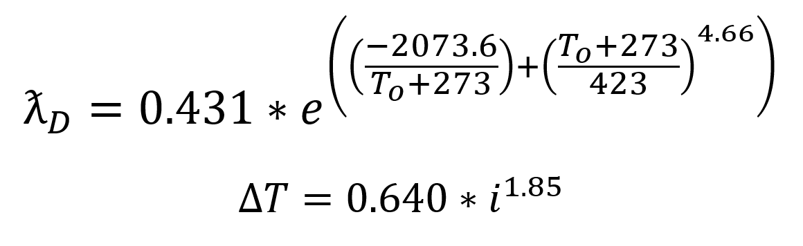
Where i is the amps per contact

And To is ambient temperature plus insert temperature rise

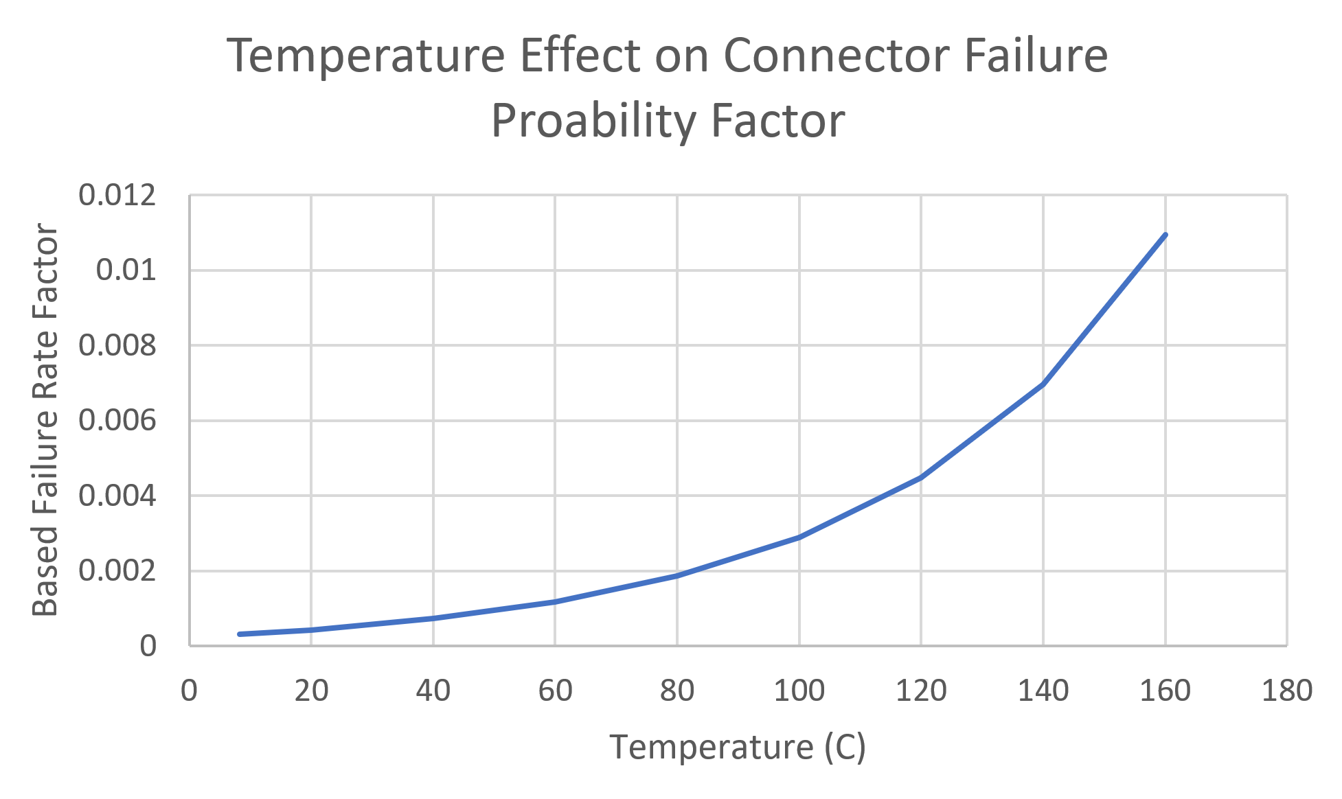
Plugging in the parameters we find that ƛD= 0.000316. Looking further into this information and failure probability model, we see that there is a correlation between the increase in temperature and the proposed failure rate. Comparing a connector that is used in an operational temperature of 20°C with one that is at 120°C, we find that the 120°C connector has a 10 times greater failure rate. If the temperature is increased another 20°C (to 140oC), then the failure rate increases to 15 times that of the connector at 20°C.

While this is a generalized model, this model suggests that if given the choice between routing power through one connector versus two connectors as a means of reducing the temperature, there could be a sizable reliability improvement simply by splitting the power out. Another option would be to use a connector with larger contacts to reduce the temperature increase.

Connectors
Is a common factor among electrical components that they degrade with exposure to elevated temperatures. Understanding how much of an impact temperature has can help you better predict the remaining reliability of your components.

Mating Factor

The mating factor of the connector failure model is straightforward: how frequently is the connector disconnected and reconnected? As one would expect, the more frequent the demating and mating of a connector, the more likely it is to suffer the failure. Interestingly, the mating/demating failure factor, has a limited impact. Connectors that are frequently mated only have a four times greater failure rate than those that are infrequently mated.

Active Pins Factor

The number of active pins in a connector has a direct correlation to the failure factor associated with it. An interesting point about the active pins calculation is the active contact count includes any conductive element in the connector that mate to transferring electrical energy. For coaxial and triaxial connectors, this formulation includes the shield contact as an active contact.

Environmental Factor

The environmental factor used in the model covers the expected environmental conditions for both ground-based, naval, and airborne applications. The partitioning of airborne applications includes climate-controlled environments, as well as uncontrolled environments of the aircraft.

Environment

MIL-SPEC

Lower Quality

Airborne: inhabited/cargo

3.0

12

Airborne: inhabited/fighter

5.0

18

Airborne: uninhabited/cargo

8.0

17

Airborne: uninhabited/fighter

12.0

25

Airborne: Rotary/winged

19.0

37

One interesting item to note in the MIL-HDBK-217 table provides different loading factors based on the quality control system used in the component manufacturing. Those materials that are identified as MIL SPEC parts have a greater reliability factor, whereas non-controlled parts, on average, are assigned a 2 to 5 times greater expected failure rate. While the handbook specifically identifies military specification as the preferred quality control process, other quality control processes that regularly evaluate performance should be considered here.

Conclusion

Using the MIL-HDBK-217 as a basis, it is very easy to develop a conservative estimate on component reliability and the associated failure rates. For those seeking aircraft certification, if no data is available on the failure rates of parts, this handbook can be a good first step. However, as the field data becomes available, the model and the numbers should be updated to reflect actual failure rates.

Keep in mind that these failure rates are the random failure rates of a component and do not consider the degradation that may occur during use. To understand how quickly these failure rates can change requires more analysis of your particular application. This is an area that Lectromec has specialized in for the last 30 years: understanding EWIS component degradation. Contact us today to discuss your application needs.

Michael Traskos

Michael Traskos

President, Lectromec

Michael has been involved in wire degradation and failure assessments for more than a decade. He has worked on dozens of projects assessing the reliability and qualification of EWIS components. Michael is an FAA DER with a delegated authority covering EWIS certification and the chairman of the SAE AE-8A EWIS installation committee.