View Latest Blog Entries
Close
Categories
Testing & Assessment Certification Standard & Regulation Aging Wires & Systems Maintenance & Sustainment Management Conference & Report Protection & Prevention Research Miscellaneous Arcing
Popular Tags
Visual Inspection High Voltage AS50881 MIL-HDBK MIL-HDBK-525 FAR AS4373 Maintenance Electromagnetic Interference (EMI) FAR 25.1707 Wire System Arcing Damage
All Tags in Alphabetical Order
2021 25.1701 25.1703 abrasion AC 33.4-3 AC 43 Accelerated Aging accessibility ADMT Aging Systems AIR6808 AIR7502 Aircraft Power System aircraft safety Aircraft Service Life Extension Program (SLEP) altitude arc damage Arc Damage Modeling Tool Arc Fault (AF) Arc Fault Circuit Breaker (AFCB) Arc Track Resistance Arcing Arcing Damage AS22759 AS22759/87 AS23053 AS29606 AS4373 AS4373 Method 704 AS50881 AS5692 AS6019 AS6324 AS81824 AS83519 AS85049 AS85485 AS85485 Wire Standard ASTM B355 ASTM B470 ASTM D150 ASTM D2671 ASTM D8355 ASTM D876 ASTM F2639 ASTM F2696 ASTM F2799 ASTM F3230 ASTM F3309 ATSRAC Attenuation Automated Wire Testing System (AWTS) Automotive Avionics backshell batteries bend radius Bent Pin Analysis Best of Lectromec Best Practice bonding Cable Cable Bend cable testing Carbon Nanotube (CNT) Certification cfr 25.1717 Chafing Chemical Testing Circuit Breaker circuit design Circuit Protection cleaning clearance Coaxial cable cold bend collision comparative analysis Compliance Component Selection Condition Based Maintenance Conductor Conductor Testing conductors conduit Connector Connector rating connector selection connector testing connectors contacts Corona Corrosion Corrosion Preventing Compound (CPC) corrosion prevention Cracking creepage D-sub data analysis data cables degradat Degradation Delamination Derating design safety development diagnostic Dielectric breakdown dielectric constant Dimensional Life disinfectant Distributed Power System DO-160 dry arc dynamic cut through E-CFR electric aircraft Electrical Aircraft Electrical Component Electrical Power Electrical Testing Electrified Vehicles Electromagnetic Interference (EMI) Electromagnetic Vulnerability (EMV) Electrostatic Discharge EMC EMF EN2235 EN3197 EN3475 EN6059 End of Service Life End of Year Energy Storage engines Environmental Environmental Cycling environmental stress ethernet eVTOL EWIS certification EWIS Component EWIS Design EWIS Failure EWIS sustainment EWIS Thermal Management EZAP FAA FAA AC 25.27 FAA AC 25.981-1C FAA Meeting failure conditions Failure Database Failure Modes and Effects Analysis (FMEA) FAQs FAR FAR 25.1703 FAR 25.1707 FAR 25.1709 Fault fault tree Fixturing Flammability fleet reliability Flex Testing fluid exposure Fluid Immersion Forced Hydrolysis fuel system fuel tank ignition Functional Hazard Assessment functional testing Fundamental Articles Fuse Future Tech galvanic corrosion Glycol Gold Gold plating Green Taxiing Grounding hand sanitizer handbook Harness Design harness protection hazard Hazard Analysis health monitoring heat shrink heat shrink tubing high current high Frequency high speed data cable High Voltage High Voltage Degradation HIRF History Hot Stamping Humidity Variation HV connector HV system ICAs IEC 60851 IEC60172 IEEE immersion insertion loss Inspection installation installation safety Instructions for Continued Airworthiness insulating material insulating tape Insulation insulation breakdown insulation resistance insulation testing interchangeability IPC-D-620 ISO 17025 Certified Lab ISO 9000 J1673 Kapton Laser Marking life limit life limited parts Life prediction life projection Lightning lightning protection liquid nitrogen lithium battery lunar Magnet wire maintainability Maintenance Maintenance costs Mandrel mean free path measurement mechanical stress Mechanical Testing MECSIP MIL-C-38999 MIL-C-85485 MIL-DTL-17 MIL-DTL-23053E MIL-DTL-3885G MIL-DTL-38999 MIL-E-25499 MIL-HDBK MIL-HDBK-1646 MIL-HDBK-217 MIL-HDBK-454 MIL-HDBK-516 MIL-HDBK-522 MIL-HDBK-525 MIL-HDBK-683 MIL-STD-1353 MIL-STD-1560 MIL-STD-1798 MIL-STD-464 MIL-T-7928 MIL-T-7928/5 MIL-T-81490 MIL-W-22759/87 MIL-W-5088 MIL–STD–5088 Military 5088 modeling moon MS3320 NASA NEMA27500 Nickel nickel plating No Fault Found OEM off gassing Outgassing Over current Overheating of Wire Harness Parallel Arcing part selection Partial Discharge partial discharge at altitude Performance physical hazard assessment Physical Testing polyamide polyimdie Polyimide-PTFE Power over Ethernet power system Power systems predictive maintenance Presentation Preventative Maintenance Program Probability of Failure Product Quality PTFE pull through Radiation Red Plague Corrosion Reduction of Hazardous Substances (RoHS) regulations relays Reliability Research Resistance Revision C Rewiring Project Risk Assessment S&T Meeting SAE SAE Committee Sanitizing Fluids Secondary Harness Protection separation Separation Requirements Series Arcing Service Life Extension Severe Wind and Moisture-Prone (SWAMP) Severity of Failure shelf life Shield Shielding Shrinkage signal signal cable Silver silver plated wire silver-plating skin depth skin effect Small aircraft smoke Solid State Circuit Breaker Space Certified Wires Splice standards Storage stored energy superconductor supportability Sustainment System Voltage Temperature Rating Temperature Variation Test methods Test Pricing Testing testing standard Thermal Circuit Breaker Thermal Endurance Thermal Index Thermal Runaway Thermal Shock Thermal Testing tin Tin plated conductors tin plating tin solder tin whiskering tin whiskers top 5 Transient Troubleshooting TWA800 UAVs UL94 USAF validation verification video Visual Inspection voltage voltage differential Voltage Tolerance volume resistivity vw-1 wet arc white paper whitelisting Winding wire Wire Ampacity Wire Bend Wire Certification Wire Comparison wire damage wire failure wire performance wire properties Wire System wire testing Wire Verification wiring components work unit code

Connector Failure Rates – Part #1

Certification

Coming up with failure rates of electrical components is always a difficult task. Historically, when failure modes and effects analyses were created for aircraft systems, the level of detail of EWIS component failures were severely lacking. Some organizations would create a single failure number for an entire circuit, regardless of the wires or connections made in that circuit.

Using modern tools and design technologies makes it possible to have a more thorough evaluation and accurate representation of the EWIS failure rates within fault trees. This still presents an issue with gathering the necessary information to determine what is the best failure rate to use. One often cited standard is the military handbook MIL-HDBK-217. Although this document has not been updated in years, it still is a useful data source. Here we review the failure rate presented for circular connectors and what this suggests when used on aircraft.

Background

The purpose of the MIL-HDBK-217 is to “establish and maintain consistent and uniform methods for estimating the inherent reliability of military electronic equipment and systems”. Further, the handbook provides a common basis for predicting future maintenance needs. Those who have maintained any platform will acknowledge that proactive maintenance is the best way to keep cost down. The handbook seeks to provide the data to make that predictive maintenance possible.

Connectors
Just like any other component, connector reliability cannot be assumed. Getting the right number into fault trees is necessary to get the best failure projection.

As identified in the introduction, the handbook has not been updated in more than two decades; the latest revision of this handbook is from 1995. Tools and technologies have significantly improved in many areas since that time and at the very least, the reliability has remained consistent if not improved. While the failure rates presented in the handbook may be a little out of date, this does provide a conservative basis for the estimation of part reliability.

Of course, failure rates do not exist in a vacuum. As additional data becomes available and service history information is thoroughly reviewed, organizations can improve or modify these models to best reflect what they see and practice. The handbook provides the general case and the general direction; it is the responsibility of the user to make it specific to the organization and application.
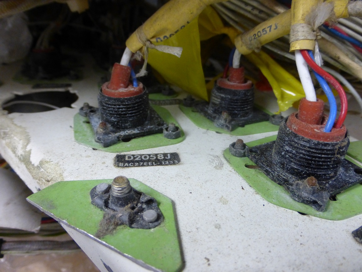
Connectors

MIL-HDBK-217 Section 15 addresses connectors. At its core, the handbook provides a formula and a set of parameters that can be used to estimate the reliability.

The first item to note here is that the failure rates presented are for mated connectors. The MIL-HDBK-217 suggests that, if a connector is attached to a Line Replaceable Unit (LRU), then the failure rate should be divided in half with the failure rate being assigned to both the LRU connector and the EWIS connector. The reason for this is to provide better reliability numbers on the LRU. EWIS engineers should be grateful to hear that they are not responsible for the full failure rate of the connector.

Failure Rate Factors

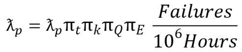
The connector failure rate presented in MIL-HDBK- 217 is comprised of four factors: the base failure rate, the active number of pins, the environmental factor, and the mating/unmating factor.

Base Failure Rate

The base failure rate factor uses the connector insert material to separate connectors into four possible groups. These groups are:

Insert Material Type

Common Insert Materials

Temperature Range (C)

A

Vitreous Glass, Alumina, Ceramic, Polyimide

-55 to 250

B

Diallylphtalate, Melamine, Fluorosilicione, Silicone, Rubber, Polysulfone

-55 to 200

C

Polyteyrafluorethylene (Teflon)

-55 to 125

D

Polyamide (Nylon), Polychloroprene (Neoprene), Polyethylene

-55 to 125

Since each of these insert materials have different temperature ranges for operation and different performance histories, there are different base failure rate formulas for each of them. Unfortunately, this creates a more difficult approximation for each configuration. The main difference between the formula is the maximum temperature rating and a couple of scalar factors.

Where this becomes more complicated is the connector temperature rise estimation. While the temperature rise within the connector can be quickly determined through laboratory testing, a generalized formulation for connector rise is difficult. Different insert materials, contact arrangements, airflow within a compartment, etc., can dramatically change the connector internal temperature. MIL-HDBK-217 guidance on estimating the temperature increase is a formula considering the combination of contact gauge and amps per contact.

Next Article

Without service data, estimations of component failure rates must use previously established best performance estimates. MIL-HDBK-217 provides a good starting basis for basic component failure rates for use in fault trees. In Lectromec’s next article, we will review some of the consequences of using this failure model and what it predicts for EWIS reliability.

Michael Traskos

Michael Traskos

President, Lectromec

Michael has been involved in wire degradation and failure assessments for more than a decade. He has worked on dozens of projects assessing the reliability and qualification of EWIS components. Michael is an FAA DER with a delegated authority covering EWIS certification and the chairman of the SAE AE-8A EWIS installation committee.