
Use of Cables on Aircraft - Part 2
In this article, we will continue the discussion by exploring the NEMA27500 cable. Four sections were covered in the previous article (Specification, identification and shield coverage, conductor size, and wire specification). Editor’s note: Since that article was published, we have also added several tables to help with part identification.
To recall, here is the NEMA27500 cable example that was discussed in part I as we proceed with examining the last three sections of cable.
|
M27500 |
H |
20 |
DC |
15 |
T |
24 |
|
Specification Part Number |
Cable Identification and Shield Coverage |
Conductor Size |
Wire Specification |
Number of Wires |
Shielding Material |
Jacket Material |
5 - Number of Wires
This one is fairly self-explanatory. The number here identifies the quantity of individual wires in the cable. The NEMA27500 standard limits this to no more than 15 wires per cable (in our example, the cable specification had 15 wires). While it is possible to have a single basic wire cable, the NEMA27500 specification requires that a single wire have an additional component such as a shield or jacket.
6 - Shielding Materials
A NEMA27500 cable may either by shielded or unshielded. For those that are shielded, there are different means of applying a shield to a cable. The two most common types are tape-wrapped shielding and woven mesh shielding. Shielding that employs a tape-wrap are usually effective at protecting Electromagnetic Interference (EMI) from high-frequencies. The woven mesh shielding is more effective at lower frequencies.
When selecting the shield, what coverage, material type, and construction are really based on the system that is being supported and the circuit EMI susceptibility. It is common to think of signal circuits as being the most commonly shielded cables, but some applications may find a benefit from shielding power wires, particularly near sensitive electrical equipment. Shielding power wires does create a scenario where a ground plane is wrapped around a current carrying wire making it easier to have an electrical short or arcing event in the case of wire damage.
Table source MIL-DTL-27500 Rev H
| Symbol for Single Shield Style | Symbol for Double Shield Style | Shield Material | Maximum Temp for Shield Material |
| U | --- | No shield | --- |
| T | V | Tin-coated copper, round | 150°C (302°F) |
| S | W | Silver-coated copper, round | 200°C (392°F) |
| N | Y | Nickel-coated copper, round | 260°C (500°F) |
| F | Z | Stainless Steel, round | 400°C (752°F) |
| C | R | Heavy Nickel coated copper, round | 400°C (752°F) |
| M | K | Silver-coated high strength copper alloy, round | 200°C (392°F) |
| P | L | Nickel-coated high strength copper alloy, round | 260°C (500°F) |
| G | A | Silver-coated copper, flat | 200°C (392°F) |
| H | B | Silver-coated high strength copper alloy, flat | 200°C (392°F) |
| * | # | Nickel-coated copper, flat | 260°C (500°F) |
| J | D | Tin-coated copper, flat | 150°C (302°F) |
| E | X | Nickel-coated high strength copper alloy, flat | 260°C (500°F) |
| I | Q | Nickel-chromium alloy, flat | 400°C (752°F) |
One concern with using shielded materials is the weight. Each additional foot of shielded cable come with a weight penalty that varies based on the shielding needs and the type of metal used. For those that are looking for viable options for weight reduction, metalized fibers or carbon nanotube fibers should be considered (these options would require non-27500 style cables).
7 - Jacket Materials
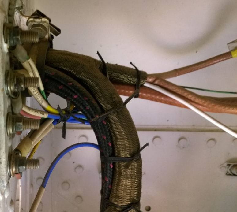
When selecting cables and evaluating the quality of construction, the quality of the shielding is an excellent place to start; this is among the most difficult parts of cable construction and a quality cable producer can really stand out here. Inherently, the process of weaving the shield conductors is an abrasive process and can cause abrasion between the shield strands and damaged the plating. This damaged plating can expose the substrate and lead to corrosion. For silver plated shielding, the potential for red-plague exists.
Some cable processors have gone to great lengths to improve this shielding process and reduce the frequency of damage shield plating. The expectation should be that there is some damage to the shield plating, but the scale of damage can vary significantly between producers.
The selection of jacket materials should be considered just as important to fluid and mechanical resistance as the single wire primary insulation. This is the surface that will interact most with the installed environment. Because of this, great care should be given to the jacket selection. Many jacket types that are available in the NEMA27500 standard are those that are common to the AS22759 family of wires (e.g. PTFE, XL-ETFE, Polyimide-PTFE). The lessons learned and application considerations for single wires insulated with these materials can also be applied to the cables that employ them for jacket protection too.
Table source MIL-DTL-27500 Rev H
|
Single Jacket Symbol |
Double Jacket Symbol |
Jacket Material |
Temperature Limit for Jacket Material |
| 00 | 00 | No Jacket | --- |
| 01 | 51 | Extruded white polyvinyl chloride (PVC) | 90° C (194°F) |
| 02 | 52 | Extruded clear polyamide in accordance with ASTM D4066 | 105°C (221°F) |
| 03 | 53 | White polyamide braid impregnated with clear polyamide finisher over a polyester tape | 105°C (221°F) |
| 04 | 54 | Polyester braid impregnated with high temperature finishers over polyester tape | 150°C (302°F) |
| 05 | 55 | Extruded Clear fluorinated ethylene propylene (FEP) | 200°C (392°F) |
| 06 | 56 | Extruded or taped and heat sealed white polytetrafluoroethylene (PTFE) | 260°C (500°F) |
| 07 | 57 | White polytetrafluoroethylene (PTFE) treated glass braid impregnated and coated with polytetrafluoroethylene finisher over presintered polytetrafluoroethylene tape | 260°C (500°F) |
| 08 | 58 | Cross linked white extruded polyvinylidene fluoride (PVF) | 150°C (302°F) |
| 09 | 59 | Extruded white fluorinated ethylene propylene (FEP) | 200°C (392°F) |
| 10 | 60 | Extruded clear polyvinylidene fluoride (PVF) | 125°C (257°F) |
| 11 | 61 | Tape of natural polyimide combined with clear fluorinated ethylene propylene (FEP) wrapped and heat sealed with (FEP) outer surface | 200°C (392°F) |
| 12 | 62 | Tape of natural polyimide combined with fluorinated ethylene propylene (FEP) wrapped and heat sealed with polyimide outer surface | 200°C (392°F) |
| 14 | 64 | Extruded white ethylene-tetrafluoroethylene copolymer (ETFE) | 150°C (302°F) |
| 15 | 65 | Extruded clear ethylene-tetrafluoroethylene copolymer (ETFE) | 150°C (302°F) |
| 16 | 66 | Braid of aromatic polyamide with high temperature finisher over presintered polytetrafluoroethylene (PTFE) tape | 200°C (392°F) |
| 17 | 67 | White extruded ethylene chlorotrifluoro-ethylene (ECTFE) | 150°C (302°F) |
| 18 | 68 | Clear extruded ethylene chlorotrifluoro-ethylene (ECTFE) | 150°C (302°F) |
| 20 | 70 | Extruded white perfluoroalkoxy (PFA) | 260°C (500°F) |
| 21 | 71 | Extruded clear perfluoroalkoxy (PFA) | 260°C (500°F) |
| 22 | 72 | Tape of polyimide combined with clear fluorinated ethylene propylene (FEP) wrapped and heat sealed with opaque polyimide outer surface | 200°C (392°F) |
| 23 | 73 | White, crosslinked, extruded, modified, ethylene-tetrafluoroethylene copolymer (XLETFE) | 200°C (392°F) |
| 24 | 74 | Tape layer of white polytetrafluoroethylene (PTFE) wrapped over a tape layer of natural polyimide combined with FEP and heat sealed. | 200°C (392°F) |
Evaluation of Cables
The use of cables can ease design, installation and provide additional benefits, such as shielding and additional layers of physical protection. The upfront negative of cables is the initial cost, but when selecting cables for applications, the potential time savings associated with implementation should also be considered.
In the next article, we will discuss some of the tests methods that cables must be exposed to as part of the testing and certification process. If you would like a jump start on this, check out Lectromec’s test listing.