
First-Article Testing of Wire Harnesses
Executive Summary
First-article testing of a wire harness is not a single prescribed test; it is a three-layer system-level verification plan that relies on:
- A first article documentation framework
- An assembly workmanship/acceptance framework,
- A set of inherited test methods adapted to evaluate the completed harness.
For aerospace, AS9102C defines how first-article inspections are to be performed and documented. Because the AS9102 is generalized, the specific means of assessment requires implementers to source technical content from standards such as IPC/WHMA-A-620F, NASA-STD-8739.4A, MIL-DTL-3885H, AS4373, etc.
Standards and Test Basis
In practice, first-article paperwork usually starts with SAE International AS9102C, workmanship and acceptance with IPC and the Wire Harness Manufacturers Association in IPC/WHMA-A-620F, mission-workmanship requirements from NASA (NASA-STD-8739.4a), military cable-assembly baselines, and component performance requirements. The AS9102C establishes how FAI (First-Article Inspection) is performed and documented, while IPC/WHMA-A-620F supplies the main consensus acceptance standard for cable and wire harness assemblies. Where uncommon or specialized designs are needed, custom acceptance criteria may need to be implemented.
The key is that harness first-article plans usually adapt existing wire, cable, and connector tests rather than invent new harness-only methods. Standards such as AS4373, ASTM D3032, and EIA-364 are often used for this purpose. AS4373 is a general aerospace wire test-method standard, ASTM D3032 explicitly applies not only to single insulated conductors but also to assemblies such as cable bundles and harnesses, and EIA-364 test methods are connector tests that can be adapted to meet harness requirements. In other words, the completed harness is tested as the place where all of those inherited component assumptions meet, or where the reduced engineering margins are verified.
What a Harness FAI Should Actually Measure
A rigorous harness FAI uses the completed assembly as the unit under test, but the test logic still comes from inherited component methods.
Pin-to-pin continuity (Low Voltage Testing). The purpose is to verify the connections, detect opens, miswires, reversals, and establish whether contact-plus-conductor resistance is acceptable. Typical practice is to use fixture-based automated analyzers with mating interfaces rather than direct probing; NASA explicitly prohibits the use of hand probes directly in harness connectors, and commercial harness analyzers routinely document continuity, resistance, miswires, and isolation. Acceptance criteria are usually drawing- or program-specific; for example, NASA requires point-to-point continuity but does not assign a universal ohmic limit.
Circuit isolation, hipot, and insulation resistance. Separate from pin-to-pin continuity, the circuit isolation tests seek to determine if there is sufficient physical separation between conductors. The NASA-STD-8739.4A gives a complete acceptance sequence and acceptance values: continuity first, then dielectric-withstanding-voltage (DWV) , then insulation resistance (IR).
- DWV is 1050 ± 50 Vrms at 60 Hz or 1500 ± 75 Vdc, or the lower value defined by the connector/cable/wire datasheet; dwell is at least 5 seconds with a ramp rate of at least 500 V/s; leakage current must not exceed 1 mA;
- IR is measured at 500 Vdc until stabilized, not exceeding 1 minute, with a minimum of 100 MΩ.
The AS9102 and IPC do not provide universal voltages, so customer requirements or the lowest-rated component will dictate the applied voltage on a circuit. Common failure modes that are detected with this testing include:
- Nicked insulation
- Stray wire strands
- Conductive contamination
- Inadequate spacing
- Shield termination issue
If a test article fails here, the cause is usually workmanship based.
Moisture proofness. Moisture testing matters whenever the harness contains rear seals, overmolds, potted transitions, solder sleeves, splices, boots, or material that could wick fluids. The procedure typically consists of multiple steps that include:
- Continuity/IR/DWV,
- Humidity cycling or direct immersion,
- Post-exposure electrical retest and visual inspection.
MIL-STD-202 Method 106 provides a cyclic moisture-resistance basis, and Method 104 (Immersion) is often used because immersion will aggravate incipient defects in seals. Acceptance criteria are commonly post-exposure measurements of continuity, IR, and hipot plus no visible ingress, corrosion, swelling, or seal displacement. Typical failures include rear-seal leakage, wicking through splices, corrosion at shield terminations, and overmold voids. In FAI, those results usually drive changes in sealing architecture and potentially process tweaks.
Partial discharge for high-voltage harnesses. For HV harnesses, continuity and hipot are necessary but not sufficient. IEC 60270 defines the charge-based Partial Discharge (PD) measurement methodology for components and systems. In practice, the voltage is increased until PD starts, then reduced until it extinguishes (PDIV (Partial Discharge Inception Voltage) and PDEV (Partial Discharge Extinction Voltage), respectively). When performed, the harness PD performance can be impacted by the system level factors and installation environment. Factors such as altitude, voltage waveform, and temperature, all influence the test results. Acceptance criteria are usually program-specific rather than standards-generic. A sound engineering rule is that PDEV should remain above maximum operating voltage with margin; otherwise, discharge initiated by a voltage transient can continue in service.
The common failure modes detected with the PD testing are voids in potting compound, sharp field concentrations, contamination, inadequate creepage/clearance, and pressure-sensitive connector interfaces (most of these issues are at or near the terminations). Those are precisely the defects that a harness FAI should aim to expose before production.
Shield effectiveness. Shielding is one of the most frequently over-simplified parts of a harness FAI. IEC 62153-4-3, -4-7, and -4-15 are usually more relevant at the harness level because they address transfer impedance, screening attenuation, and coupling attenuation of cable shields, mated screened connectors, and cable assemblies. If the question is system susceptibility rather than direct attenuation, ISO 11452-4 and SAE J1113/4 provide BCI (bulk current injection) methods that couple RF (radio frequency) onto the harness itself.
The acceptance criteria for shield effectiveness are (again) program-specific. Frequent failure modes detected with these tests are bad pigtail terminations, poor shell bonding, braid discontinuities, high backshell-to-shell resistance, and weak connector transitions. Design teams often discover here that a cable that looked “shielded” on paper became a poor shield after termination.
Thermal Cycling. The purpose of thermal cycling in harness FAI is to force differential expansion and contraction across components. Typical aerospace and military harness FAIs do not use a single harmonized profile; instead, specifications like EIA-364-32 thermal shock/temperature for connectors can be modified for harness test needs. These thermal cycling test will typically have 5 stages:
- Heat up
- Dwell at high target temperature until the entire system reaches thermal equilibrium
- Move to ambient conditions or to a low temperature freezer.
- Dwell at low target temperature until the entire system reaches thermal equilibrium.
- Rest at ambient then repeat or repeat immediately.
Thermal performance under load. Thermal FAI is most useful on power harnesses, tightly bundled routes, and connector-dense assemblies. Connector standards assess current-carrying capacity through temperature-rise and current-temperature-derating tests, and that logic adapts well to harnesses. For FAI testing, this should seek to apply worst-case simultaneous currents, instrument the highest-risk regions, wait for stabilization, and then repeat electrical checks and measure voltage drop.
The maximum allowable temperature rise is usually dictated by a combination of factors that include component limits, operational ambient temperature derating, and derating for safety. The most revealing locations for temperature monitoring are contact interfaces, splice bodies, branches within dense bundle cores, and backshell exits. Common failures found with this test method are hot contacts, undersized wire, unbalanced current paths, and local overheating near sleeving or seals. These are split between design and manufacturing issues, not merely test anomalies.
Recommended First-Article Sequence
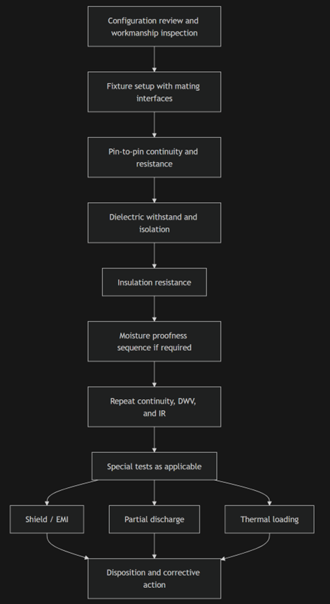
The most effective sequence starts with low-energy verification, then adds higher electrical stress, environmental or application-specific stresses, and finally repeats the core electrical checks. That sequencing is consistent with NASA’s continuity → DWV → IR order and with the broader AS9102 principle that first article results must remain traceable back to the specific assembly tested.
Conclusion
The practical implication is straightforward: a credible harness FAI is rarely just a continuity check. Electrically, a starting point is pin-to-pin continuity (voltage drop) along with circuit isolation, dielectric withstand, and insulation resistance. If the harness contains sealed interfaces, overmolds, boots, splices, or operates in moisture-prone environments, assessment of moisture proofness becomes essential. Harnesses designated for high-voltage applications should consider partial discharge evaluations under representative altitude and temperature conditions. Shielded harnesses often warrant transfer-impedance, coupling-attenuation, or bulk-current-injection work, and high-current or tightly bundled harnesses may need thermal loading on worst-case simultaneous circuits. The common thread is that harness FAIs usually adapt existing component-level tests to the finished assembly and its actual geometry.