
Voltage, Current, and Thermally Rating Connectors
While electrical component qualification is nothing new to the aerospace industry, the emerging trend toward full aircraft electrification requires every component to be electrically connected; for most equipment, this means incorporation of electrical connectors. Weight, cost, reliability, and performance are the four most common elements initially considered in connector selection, but the finer details of electrical connectors use must also be considered. Here, we discuss how one might go about qualifying an electrical connector, specifically, to address its voltage, current, and thermal limitations.
Where to Start
The best starting point to define these parameters is with the MIL-DTL-38999 and AS39029 standards (the MIL-C-39029 has been moved to the SAE – you can still get an old copyright-free version). For those unfamiliar, the MIL-DTL-38999 has been an industry standard for decades and has impacted electrical connector design for aerospace vehicles for generations. This is a good starting point to learn about standard tests that are required for generalized aircraft connectors.
Many of the stressor tests (environmental, thermal, etc.) have parameters that can be considered excessive for benign aircraft environments. After all, these are military specification connectors and are expected to work in harsh environments. As such, those applying these tests to more benign conditions should look to align the test parameters for the intended application.
Voltage
| Altitude | Service rating M | Service rating N | Service rating I | Service rating II | ||||
|---|---|---|---|---|---|---|---|---|
| Mated | Unmated | Mated | Unmated | Mated | Unmated | Mated | Unmated | |
| Sea level | 1300 | 1300 | 1000 | 1000 | 1800 | 1800 | 2300 | 2300 |
| 50,000 feet | 800 | 550 | 600 | 400 | 1000 | 600 | 1000 | 800 |
| 70,000 feet | 800 | 350 | 600 | 260 | 1000 | 400 | 1000 | 500 |
| 100,000 feet | 800 | 200 | 600 | 200 | 1000 | 200 | 1000 | 200 |
Section 3.4.1.4 of MIL-DTL-38999 elaborates on voltage rating. The provided table shows the test voltages for both mated and unmated connectors. The expectation is that the test should identify any “disruptive discharge”. For those familiar with Lectromec’s articles on high voltage, there are two threat modes for partial discharge: through the material or on the surface.
Consideration of Functionality
Beyond standard voltage application on the connectors is also important when selecting connectors. The test methods identified in MIL-DTL-38999 are focused on lower voltage systems, specifically, those below 300 volts. Above 300 volts, factors such as partial discharge need to be considered and should be assessed during the voltage application in testing. If partial discharge is not measured during the test, and only the leakage current between two pins (or pins and shell) is captured, test results may yield an incorrect safe operational voltage assessment for the connector.
Because the connectors are used for aerospace applications, testing at reduced air pressure is important. As can be seen from the included table, the test voltage of an unmated connector drops by more than 50% for every connector type when tested at 50kft relative to its sea level test voltage. The performance change can be dramatic, and a factor worthy of determining through testing. For further information on how altitude can impact partial discharge, see this article.
Furthermore, the type of voltage applied can impact performance. In application, if different voltage waveforms beyond AC are used, such as high frequency or pulse width modulation, this may impact the connector longevity. From a general test and performance perspective, this risk of impact may limit the actual test application to just 60 Hertz; in such a case, the deviations from the standard testing voltage should be identified in the product specification. For the specific application, testing should be carried out to verify performance with the operational voltage/ frequency and include vehicle environmental and electrical factors such as electrical transients (voltage spikes), temperature, and altitude.
Connector Current Rating
Consideration of connector current rating can be broken down into two parts: the current rating of the contact and the current rating of the connector as a whole.
Tests in AS39029 evaluate the current rating of the contact. Testing primarily consists of a progressive increase in current on the contact under test until the maximum temperature is attained.
As with any other property, the current rating of the connector can become more complicated as the number of powered circuits can impact this. The effort of testing all circuits on a connector with up to five contacts may be relatively simple, but quickly becomes impractical as the number of contacts in a connector increases.
The connector current rating quickly becomes a very difficult thermal energy problem with several factors to consider:
- Where the current is flowing through the contacts,
- The contact sizing,
- The thermal transfer to the connector inserts,
- The thermal transfer to the connector shell,
- The equipment to which the connectors are mounted,
- The thermal transfer down the wires and cables that are connected to the connector,
- Air flow,
- Material properties of every relevant piece of equipment,
- Ambient temperature conditions, and
- Static and dynamic electrical loads
These all have an impact on the maximum current that can be carried by the connector. There is not a standard formula that has been able to capture all of these factors like those in AS50881 for wire bundle current derating. The most effective way to gather the electrical limits is to spend a day or two in the lab to generate the data.
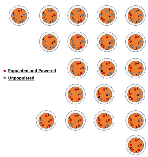
Consider the possible electrical load tests for a single 5-pin connector. To simplify the number of possible configurations, the example shall only consider:
- Connectors with more than one populated pin always have pin ‘A’ populated.
- Does not consider pins that are populated but unpowered.
- Assumes that all powered circuits have the same current.
Even with these simplifying assumptions, there are 20 potential configurations. It is possible that most of the similar configurations will yield similar results. If the temperature increases in the connector does not come close to the maximum temperature rating, simplifying assumptions can be employed. However, as the design gets closer to the maximum temperature, the test will have to represent electrical and environmental conditions more closely.
Thermal
Temperature rating is handled typically by looking at the weakest part of the connector construction (thermally) and setting the maximum temperature below that. The limit might be based on plating, adhesive, mechanical performance, etc. If there is no data, then thermal tests should start with an educated guess and increase or decrease the exposure temperature based on the connector performance in thermal shock or thermal cycling tests.
The pass criteria for the thermal cycling test gives general requirements on the post-exposure connector condition. The MIL-DTL-38999 states that, “there shall be no blistering, peeling or separation of plating or other damage detrimental to the operation of the connector.” Elements like discoloration and superficial damage are acceptable; changes to pin-to-pin resistance, for example, may suffer some degradation and that level of degradation may require additional testing and longer duration thermal exposure to understand the severity of the performance change.
The Intended Application
When setting performance levels of any of the tests discussed here, it is important to avoid creating overly severe test conditions to “see if it will fail”. If the goal is for the connector to be qualified for the general case, then this approach may require multiple test iterations, but will generate data to support the performance claims.
However, if the intended application is narrower and intended to be limited to a single aircraft or system, then the test parameters should align with the vehicle performance requirements. This objective creates different drivers on the test plan development that will push the connector to be tested below its performance capabilities, however, this reduces the potential of poor test results leading to redesign.
Summary
The voltage, current, and thermal parts of connector qualification are straight forward, but they do require some thought and planning before being implemented. In many cases, particularly with non-standard (i.e., non-60Hz and elevated voltage) power systems, there will be practical limitations as to how much testing can be performed by a supplier. The range of actual applications and systems the connector might be attached to is limitless and this means that due diligence is needed by the system integrator to ensure the connector, and wiring system, can meet the performance requirements.