View Latest Blog Entries
Close
Categories
Testing & Assessment Certification Standard & Regulation Aging Wires & Systems Maintenance & Sustainment Management Conference & Report Protection & Prevention Research Miscellaneous Arcing
Popular Tags
Visual Inspection High Voltage AS50881 MIL-HDBK MIL-HDBK-525 FAR AS4373 Electromagnetic Interference (EMI) Maintenance FAR 25.1707 Wire System Arcing Damage
All Tags in Alphabetical Order
2021 25.1701 25.1703 abrasion AC 33.4-3 AC 43 Accelerated Aging ADMT Aging Systems AIR6808 AIR7502 Aircraft Power System aircraft safety Aircraft Service Life Extension Program (SLEP) altitude arc damage Arc Damage Modeling Tool Arc Fault (AF) Arc Fault Circuit Breaker (AFCB) Arc Track Resistance Arcing Arcing Damage AS22759 AS22759/87 AS23053 AS29606 AS4373 AS4373 Method 704 AS50881 AS5692 AS6019 AS6324 AS81824 AS83519 AS85049 AS85485 AS85485 Wire Standard ASTM B355 ASTM B470 ASTM D150 ASTM D2671 ASTM D8355 ASTM D876 ASTM F2639 ASTM F2696 ASTM F2799 ASTM F3230 ASTM F3309 ATSRAC Attenuation Automated Wire Testing System (AWTS) Automotive Avionics backshell batteries bend radius Bent Pin Analysis Best of Lectromec Best Practice bonding Cable Cable Bend cable testing Carbon Nanotube (CNT) Certification cfr 25.1717 Chafing Chemical Testing Circuit Breaker circuit design Circuit Protection cleaning clearance Coaxial cable cold bend collision comparative analysis Compliance Component Selection Condition Based Maintenance Conductor Conductor Testing conductors conduit Connector Connector rating connector selection connector testing connectors contacts Corona Corrosion Corrosion Preventing Compound (CPC) corrosion prevention Cracking creepage D-sub data analysis data cables degradat Degradation Delamination Derating design safety development diagnostic Dielectric breakdown dielectric constant Dimensional Life disinfectant Distributed Power System DO-160 dry arc dynamic cut through E-CFR electric aircraft Electrical Aircraft Electrical Component Electrical Power Electrical Testing Electrified Vehicles Electromagnetic Interference (EMI) Electromagnetic Vulnerability (EMV) Electrostatic Discharge EMC EMF EN2235 EN3197 EN3475 EN6059 End of Service Life End of Year Energy Storage engines Environmental Environmental Cycling environmental stress ethernet eVTOL EWIS certification EWIS Component EWIS Design EWIS Failure EWIS sustainment EWIS Thermal Management EZAP FAA FAA AC 25.27 FAA AC 25.981-1C FAA Meeting failure conditions Failure Database Failure Modes and Effects Analysis (FMEA) FAQs FAR FAR 25.1703 FAR 25.1707 FAR 25.1709 Fault fault tree Fixturing Flammability fleet reliability Flex Testing fluid exposure Fluid Immersion Forced Hydrolysis fuel system fuel tank ignition Functional Hazard Assessment functional testing Fundamental Articles Fuse Future Tech galvanic corrosion Glycol Gold Gold plating Green Taxiing Grounding hand sanitizer handbook Harness Design harness protection hazard Hazard Analysis health monitoring heat shrink heat shrink tubing high current high Frequency high speed data cable High Voltage High Voltage Degradation HIRF History Hot Stamping Humidity Variation HV connector HV system ICAs IEC 60851 IEC60172 IEEE immersion insertion loss Inspection installation installation safety Instructions for Continued Airworthiness insulating material insulating tape Insulation insulation breakdown insulation resistance insulation testing interchangeability IPC-D-620 ISO 17025 Certified Lab ISO 9000 J1673 Kapton Laser Marking life limit life limited parts Life prediction life projection Lightning lightning protection liquid nitrogen lithium battery lunar Magnet wire maintainability Maintenance Maintenance costs Mandrel mean free path measurement mechanical stress Mechanical Testing MECSIP MIL-C-38999 MIL-C-85485 MIL-DTL-17 MIL-DTL-23053E MIL-DTL-3885G MIL-DTL-38999 MIL-E-25499 MIL-HDBK MIL-HDBK-1646 MIL-HDBK-217 MIL-HDBK-454 MIL-HDBK-516 MIL-HDBK-522 MIL-HDBK-525 MIL-HDBK-683 MIL-STD-1353 MIL-STD-1560 MIL-STD-1798 MIL-STD-464 MIL-T-7928 MIL-T-7928/5 MIL-T-81490 MIL-W-22759/87 MIL-W-5088 MIL–STD–5088 Military 5088 modeling moon MS3320 NASA NEMA27500 Nickel nickel plating No Fault Found OEM off gassing Outgassing Over current Overheating of Wire Harness Parallel Arcing part selection Partial Discharge partial discharge at altitude Performance physical hazard assessment Physical Testing polyamide polyimdie Polyimide-PTFE Power over Ethernet power system Power systems predictive maintenance Presentation Preventative Maintenance Program Probability of Failure Product Quality PTFE pull through Radiation Red Plague Corrosion Reduction of Hazardous Substances (RoHS) regulations relays Reliability Research Resistance Revision C Rewiring Project Risk Assessment S&T Meeting SAE SAE Committee Sanitizing Fluids Secondary Harness Protection separation Separation Requirements Series Arcing Service Life Extension Severe Wind and Moisture-Prone (SWAMP) Severity of Failure shelf life Shield Shielding Shrinkage signal signal cable Silver silver plated wire silver-plating skin depth skin effect Small aircraft smoke Solid State Circuit Breaker Space Certified Wires Splice standards Storage stored energy superconductor supportability Sustainment System Voltage Temperature Rating Temperature Variation Test methods Test Pricing Testing testing standard Thermal Circuit Breaker Thermal Endurance Thermal Index Thermal Runaway Thermal Shock Thermal Testing tin Tin plated conductors tin plating tin solder tin whiskering tin whiskers top 5 Transient Troubleshooting TWA800 UAVs UL94 USAF validation verification video Visual Inspection voltage voltage differential Voltage Tolerance volume resistivity vw-1 wet arc white paper whitelisting Winding wire Wire Ampacity Wire Bend Wire Certification Wire Comparison wire damage wire failure wire performance wire properties Wire System wire testing Wire Verification wiring components work unit code

Aircraft wire inspection? Time tested guidelines

Management

Performing routine aircraft wire systems visual inspections is a critical aspect of maintaining aircraft airworthiness and extending the component lifecycle. A visual inspection is the first step in assessing the condition of a component or determining what future steps need to be taken. This article discusses recommended techniques based on MIL-HDBK-522, which provides EWIS inspection guidance and lessons learned.

Inspection of Wiring from Supply System

Before performing maintenance actions to replace wires, they should be examined for any physical damage such as cuts, burns, or abrasion. The conductor should be closely examined for any corrosion, by carefully removing the insulation without causing any damage to the conductor (a properly maintained wire stripper should be able to accomplish this). Conductor discolorations or rough surfaces are good indications of corrosion. Such conductors should be discarded and not installed.

series arcing
Use wire that has been property maintained. Don’t use wire that has already been mechanical, thermally, or chemically stressed.
Source: MIL-HDBK-522

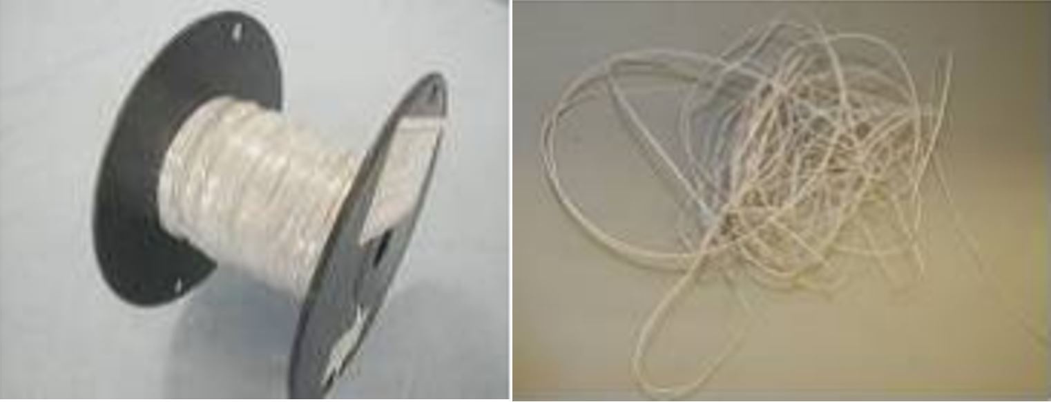
All wires must be legibly marked with an identification code. Not marking wires can result not only in the installation of unknown wires, but also in slowing down the speed of future maintenance operations (i.e., lack of clear identification will slow replacement). In the figure to the right, the image on the left shows how the wire should be received from the manufacturer—properly wrapped on a wire spool. The image on the right shows an improper way of maintaining wires as it can cause stress to the conductor and insulation for any sharp bends.

Insulation Inspection

Insulation should be carefully examined visually for cracking, heat damage, moisture/fluid damage, and mechanical damage from maintenance activities. More in depth analysis is possible with degradation assessment. Harnesses routed in SWAMP (Severe Wind And Moisture Prone) environments should be examined more frequently for these issues as these harnesses are prone to faster degradation.

series arcing
Source: MIL-HDBK-522

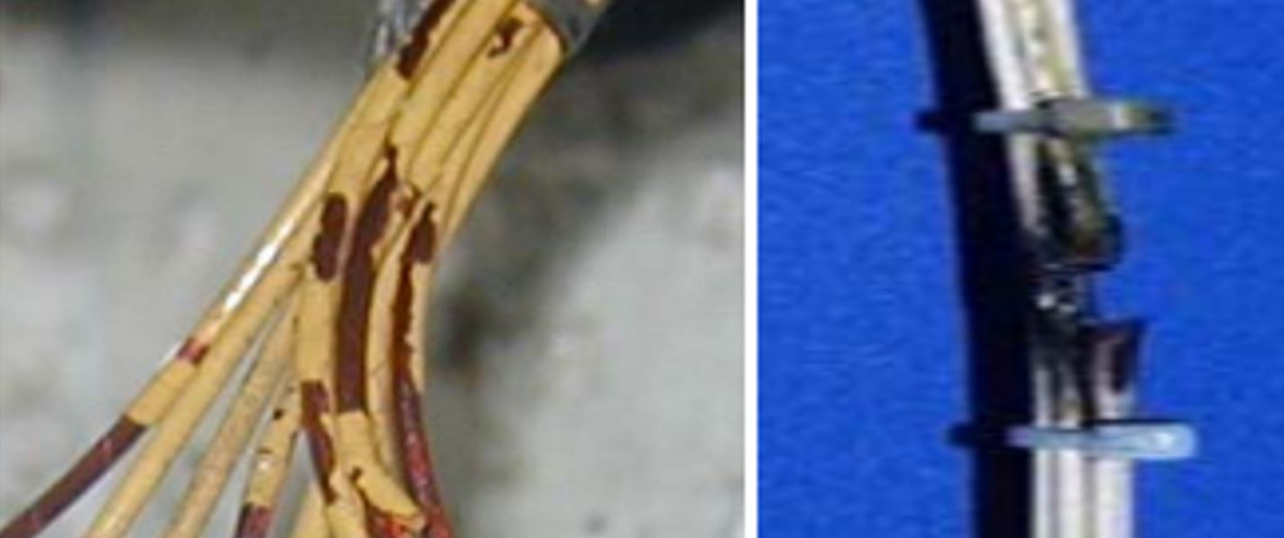
In the figure to the right, the image on the left shows that some of the insulation is flaking off, exposing the polyimide. This condition is acceptable and does not require replacement as the conductor is not exposed. However, it should be noted, and a future visual inspection should be performed to monitor the degradation. The image on the right shows the damage caused by an electrical arcing event, which causes severe damage to a wire harness.

Harness Routing Inspection

series arcing
Source: MIL-HDBK-522

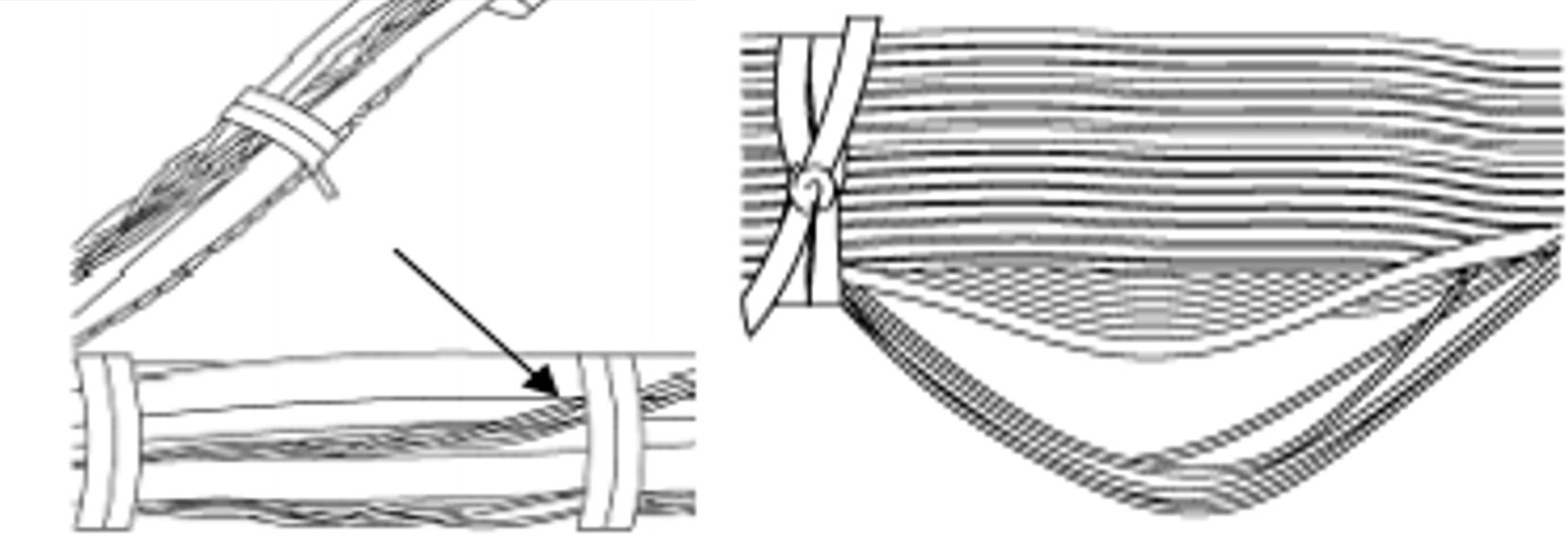
When running and/or installing harnesses, there are a few techniques that are recommended to prevent damage. Among the more obvious ones is that harnesses should be routed in a way that minimizes abrasion with other harnesses—harness-to-harness abrasion can cause rapid deterioration. Another is to have them run parallel to each other to prevent abrasion. Shown in the left side image of the figure, is a wire that has crossed over and is not running in parallel. This situation is unacceptable. When installing harnesses or making repairs, the lengths of the wires should be sufficient so that it does not result in any unnecessary tension in the harness. The wire lengths should also not be so long that it results in excess wiring. The image on the right also illustrates an unacceptable situation, where a few wires are too long causing them to separate from the harness.

Cable Protection Inspection

series arcing
Source: Lectromec

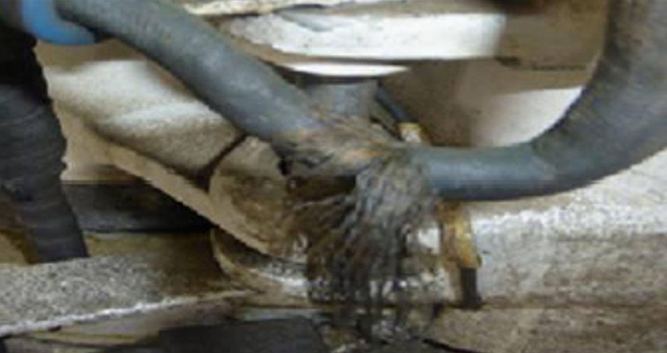
Cable protection is important in extending the lifecycle of harnesses. When performing an inspection of the cable protection, the sleeves should not be fraying (as shown in this image). Harnesses should be examined for chaffing. Chaffing is more likely to occur either when harnesses are routed close to other equipment/structures or when one harness is directly resting on another. This situation can be avoided by properly routing wires/harnesses and installing standoffs to prevent contact points. When routing harnesses, tight bends are not recommended as they can cause unnecessary stress to the wire. Sharp bends are commonly seen close to connectors. See Lectromec’s article on bend radius for more information.

Cable Clamp Inspection

series arcing
Source: Lectromec

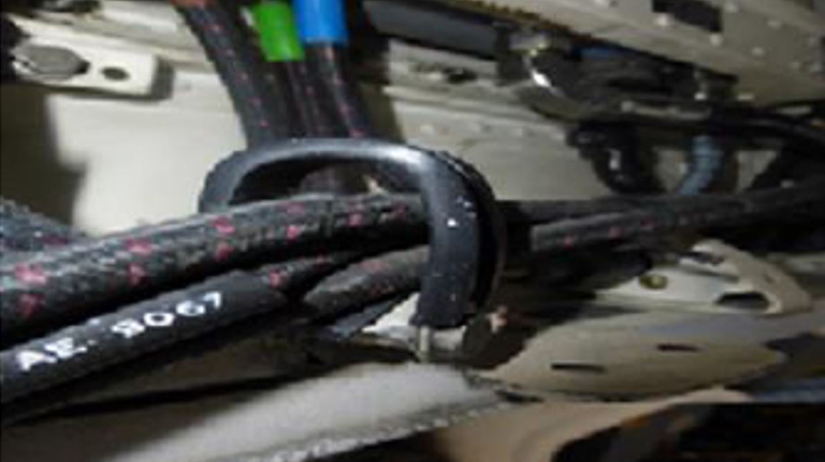
The purpose of cable clamps is to secure harnesses in place to prevent chaffing against structures. Clamps should be tightly fit to the harness size, but not so tight that they cause chaffing. This image shows a clamp that is too large for the harness size. The harness can freely move around and is not properly secured in place. The clamp itself should also be properly secured in place. A light shake of the clamps can be performed to ensure all clamps are tightly secured to the aircraft.

Summary

For more information, you can read MIL-HDBK-522, which provides excellent guidance, tips, and techniques for performing effective visual inspections.

Carina Cannon

Carina Cannon

Engineer, Lectromec

Carina is a systems engineer with experience in quality management systems, EWIS component degradation modeling, and test equipment design. Carina’s work has focused on Service Life Extension Programs (SLEP) and preparing Lectromec’s lab for formal lab certification.