View Latest Blog Entries
Close
Categories
Testing & Assessment Certification Standard & Regulation Aging Wires & Systems Maintenance & Sustainment Management Conference & Report Protection & Prevention Research Miscellaneous Arcing
Popular Tags
Visual Inspection High Voltage AS50881 MIL-HDBK MIL-HDBK-525 FAR AS4373 Maintenance Electromagnetic Interference (EMI) FAR 25.1707 Wire System Arcing Damage
All Tags in Alphabetical Order
2021 25.1701 25.1703 abrasion AC 33.4-3 AC 43 Accelerated Aging accessibility ADMT Aging Systems AIR6808 AIR7502 Aircraft Power System aircraft safety Aircraft Service Life Extension Program (SLEP) altitude arc damage Arc Damage Modeling Tool Arc Fault (AF) Arc Fault Circuit Breaker (AFCB) Arc Track Resistance Arcing Arcing Damage AS22759 AS22759/87 AS23053 AS29606 AS4373 AS4373 Method 704 AS50881 AS5692 AS6019 AS6324 AS81824 AS83519 AS85049 AS85485 AS85485 Wire Standard ASTM B355 ASTM B470 ASTM D150 ASTM D2671 ASTM D8355 ASTM D876 ASTM F2639 ASTM F2696 ASTM F2799 ASTM F3230 ASTM F3309 ATSRAC Attenuation Automated Wire Testing System (AWTS) Automotive Avionics backshell batteries bend radius Bent Pin Analysis Best of Lectromec Best Practice bonding Cable Cable Bend cable testing Carbon Nanotube (CNT) Certification cfr 25.1717 Chafing Chemical Testing Circuit Breaker circuit design Circuit Protection cleaning clearance Coaxial cable cold bend collision comparative analysis Compliance Component Selection Condition Based Maintenance Conductor Conductor Testing conductors conduit Connector Connector rating connector selection connector testing connectors contacts Corona Corrosion Corrosion Preventing Compound (CPC) corrosion prevention Cracking creepage D-sub data analysis data cables degradat Degradation Delamination Derating design safety development diagnostic Dielectric breakdown dielectric constant Dimensional Life disinfectant Distributed Power System DO-160 dry arc dynamic cut through E-CFR electric aircraft Electrical Aircraft Electrical Component Electrical Power Electrical Testing Electrified Vehicles Electromagnetic Interference (EMI) Electromagnetic Vulnerability (EMV) Electrostatic Discharge EMC EMF EN2235 EN3197 EN3475 EN6059 End of Service Life End of Year Energy Storage engines Environmental Environmental Cycling environmental stress ethernet eVTOL EWIS certification EWIS Component EWIS Design EWIS Failure EWIS sustainment EWIS Thermal Management EZAP FAA FAA AC 25.27 FAA AC 25.981-1C FAA Meeting failure conditions Failure Database Failure Modes and Effects Analysis (FMEA) FAQs FAR FAR 25.1703 FAR 25.1707 FAR 25.1709 Fault fault tree Fixturing Flammability fleet reliability Flex Testing fluid exposure Fluid Immersion Forced Hydrolysis fuel system fuel tank ignition Functional Hazard Assessment functional testing Fundamental Articles Fuse Future Tech galvanic corrosion Glycol Gold Gold plating Green Taxiing Grounding hand sanitizer handbook Harness Design harness protection hazard Hazard Analysis health monitoring heat shrink heat shrink tubing high current high Frequency high speed data cable High Voltage High Voltage Degradation HIRF History Hot Stamping Humidity Variation HV connector HV system ICAs IEC 60851 IEC60172 IEEE immersion insertion loss Inspection installation installation safety Instructions for Continued Airworthiness insulating material insulating tape Insulation insulation breakdown insulation resistance insulation testing interchangeability IPC-D-620 ISO 17025 Certified Lab ISO 9000 J1673 Kapton Laser Marking life limit life limited parts Life prediction life projection Lightning lightning protection liquid nitrogen lithium battery lunar Magnet wire maintainability Maintenance Maintenance costs Mandrel mean free path measurement mechanical stress Mechanical Testing MECSIP MIL-C-38999 MIL-C-85485 MIL-DTL-17 MIL-DTL-23053E MIL-DTL-3885G MIL-DTL-38999 MIL-E-25499 MIL-HDBK MIL-HDBK-1646 MIL-HDBK-217 MIL-HDBK-454 MIL-HDBK-516 MIL-HDBK-522 MIL-HDBK-525 MIL-HDBK-683 MIL-STD-1353 MIL-STD-1560 MIL-STD-1798 MIL-STD-464 MIL-T-7928 MIL-T-7928/5 MIL-T-81490 MIL-W-22759/87 MIL-W-5088 MIL–STD–5088 Military 5088 modeling moon MS3320 NASA NEMA27500 Nickel nickel plating No Fault Found OEM off gassing Outgassing Over current Overheating of Wire Harness Parallel Arcing part selection Partial Discharge partial discharge at altitude Performance physical hazard assessment Physical Testing polyamide polyimdie Polyimide-PTFE Power over Ethernet power system Power systems predictive maintenance Presentation Preventative Maintenance Program Probability of Failure Product Quality PTFE pull through Radiation Red Plague Corrosion Reduction of Hazardous Substances (RoHS) regulations relays Reliability Research Resistance Revision C Rewiring Project Risk Assessment S&T Meeting SAE SAE Committee Sanitizing Fluids Secondary Harness Protection separation Separation Requirements Series Arcing Service Life Extension Severe Wind and Moisture-Prone (SWAMP) Severity of Failure shelf life Shield Shielding Shrinkage signal signal cable Silver silver plated wire silver-plating skin depth skin effect Small aircraft smoke Solid State Circuit Breaker Space Certified Wires Splice standards Storage stored energy superconductor supportability Sustainment System Voltage Temperature Rating Temperature Variation Test methods Test Pricing Testing testing standard Thermal Circuit Breaker Thermal Endurance Thermal Index Thermal Runaway Thermal Shock Thermal Testing tin Tin plated conductors tin plating tin solder tin whiskering tin whiskers top 5 Transient Troubleshooting TWA800 UAVs UL94 USAF validation verification video Visual Inspection voltage voltage differential Voltage Tolerance volume resistivity vw-1 wet arc white paper whitelisting Winding wire Wire Ampacity Wire Bend Wire Certification Wire Comparison wire damage wire failure wire performance wire properties Wire System wire testing Wire Verification wiring components work unit code

Minimum bend radius as applied to aircraft wire system degradation

Protection & Prevention

Constant mechanical strain can and will reduce a wire’s longevity. Knowledge of minimum bend radius can reduce wire system degradation. These stresses can come from clamps that are too tight, over compressed harnesses protection sleeving, or poor routing. One method to reduce this potential mechanical strain in harness routing, is to ensure that all harnesses are maintaining a minimum bend radius. The basic concept of the minimum bend radius is that, when a harness must be routed around something, sufficient curvature should be maintained to prevent additional mechanical strain on the wires.

The minimum bend radius of wires and harnesses must be considered for multiple reasons:

  1. Mechanical strain on the wires: The tighter a wire is bent upon itself, the more stress is placed on the insulation. On the outside of the bend, the insulation is forced to stretch, on the inside bend, the insulation is compressed. For multilayer insulation systems, this may also cause the separation of layers and chafe points.
  2. Wire length: Wire harnesses are often manufactured to fit a particular form with slack provided to allow for wires to flex around bends. Tighter bends force the wires on the outside of the turn to travel a longer distance. This can result in an additional force being applied when mating connectors.
  3. Damage to shielding: Wires and multiple conductor cables with shielding are also susceptible to damage from too tight a bend radius. The additional strain may also cause the shielding to become less effective.

Guidance for selection of bend radius comes from the industry standard AS50881 (or OEM guidance). In this document, the recommended bend radius for wire harnesses is no less than 10x the diameter of the largest wire or cable. By maintaining this harnesses curvature, the negative effects of a tight bend radius on the wires should be mitigated.

If you are interested in wire system degradation, you may want to read the Wire Degradation and Looking in the Arc article.

Wire System Degradation

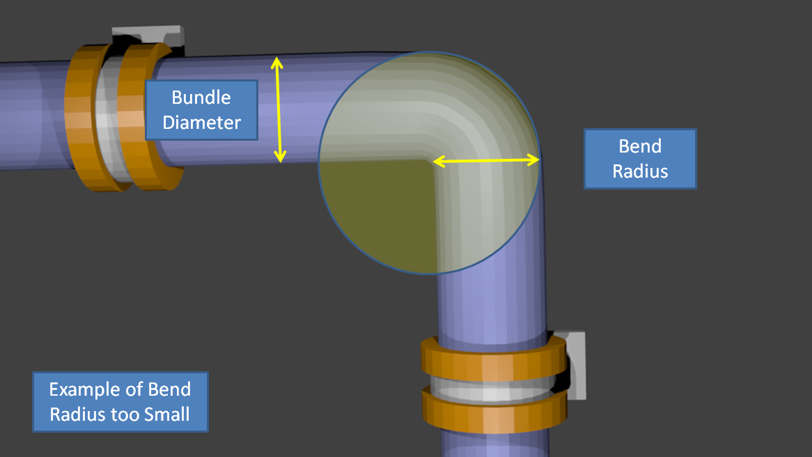
To provide a better description of what this means, the following figures show what is acceptable for harness installation. The first figure shows an example of a bend radius that is too tight. In the example, the bend radius is slightly more than the harnesses diameter.

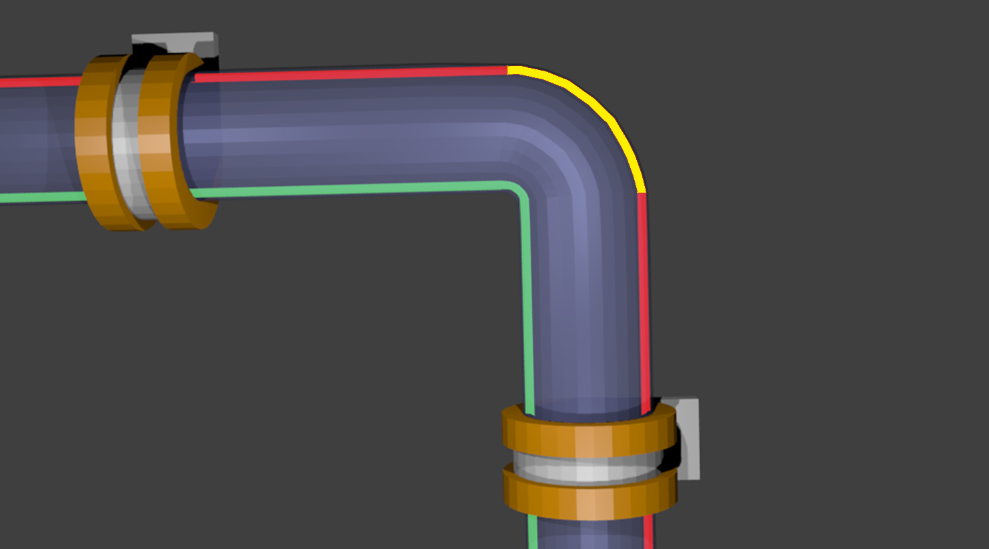
An example of how much longer the wire on the outside of the harness has to be is shown in the next figure. The green wire is on the inside of the harness with the red wire on the outside. The yellow segment of the red wire shows additional length the red wire must travel. If this harness had a 1.0 diameter, then this additional length would be 1.57inches. This may not seem like much, but if the harness is designed for a close fit, then there will be considerable strain on the red wire when the connectors are mated.

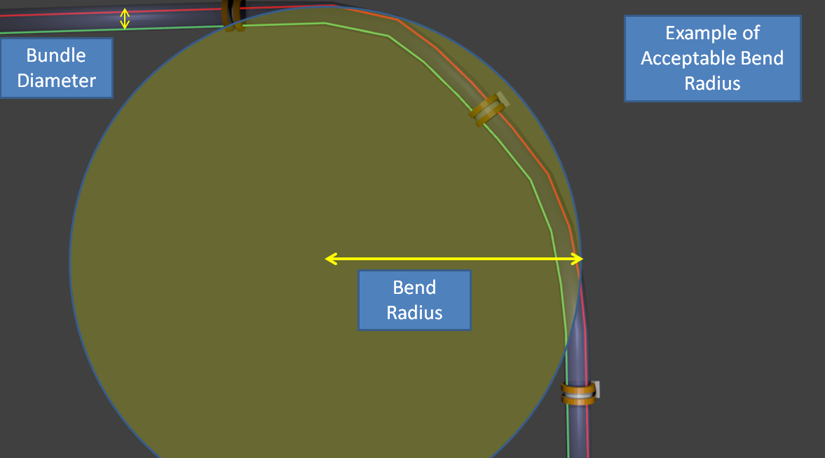
Now by expanding the harness to match the 10x requirement, there is significantly less stress on the wires. An example of an acceptable bend radius is shown in the next figure. It may also be necessary to add one or more clamps to the harness to maintain the desired curvature.

Summary

It is important to maintain an adequate bend radius for wire longevity. This may require additional clamping as to prevent sag or damage to the harness, but this will help to reduce the number of issues that may occur with a harness that is too tightly bent.

Michael Traskos

Michael Traskos

President, Lectromec

Michael has been involved in wire degradation and failure assessments for more than a decade. He has worked on dozens of projects assessing the reliability and qualification of EWIS components.