Key Takeaways
- An aircraft’s electrical wiring interconnection system (EWIS) goes beyond wire harnesses, but includes much of the supporting equipment.
- The EWIS does include engine wire harnesses.
- Modification of the EWIS does require impact analysis – the first step to understanding the impact is the with is with the review of the collocated systems.
Having well-defined and recognized system boundaries is the best means to ensure an analysis of that system is robust and does not leave any analysis gaps. Without an established limit and assigned responsibilities, arguments will ensue as to who is the responsible party and time/effort will be wasted with duplicated analysis.
Because an aircraft’s wiring touches nearly all of the systems, it can be confusing to understand where the system starts and stops, and this has led to confusion as to the responsible party for the wiring system design and/or maintenance. Some organizations have seen the responsibility fall on the electrical power systems teams, others, avionics. Regardless of who takes up the responsibility, a clear definition of the wiring system’s physical and logical boundaries must be agreed upon. Thankfully, there are several industry documents that can be relied upon.
Starting with the FAA definition
According to 25.1701(a), the electrical wiring interconnection system (EWIS) is, “any wire, wiring device, or combination of these, including termination devices, installed in any area of the airplane for the purpose of transmitting electrical energy, including data and signals, between two or more intended termination points.”
The FAA definition then goes on to list several wiring system components that are included in the EWIS definition, of particular interest is section A14 that states, “EWIS components inside shelves, panels, racks, junction boxes, distribution panels, and back-planes of equipment racks, including, but not limited to, circuit board back-planes, wire integration units, and external wiring of equipment.” From a top-level view, the statement suggests that any wiring that is not specifically located inside of equipment boxes not used for distribution are part of the EWIS.
Engines, Nacelles, and APUs
One area of contention during the original rule definition with the FAA is wiring harnesses attached to engines, nacelles, and APUs. As identified in the disposition of comments, the FAA identified that GE, Honeywell, and AIA/GAMA commented that engine, nacelle, and APUs wiring should be exempt from the EWIS certification and maintenance requirements. Specifically, the wiring in these areas is very robust and that the existing regulations (those in existence prior to the EWIS regulations released in 2007) were adequate.
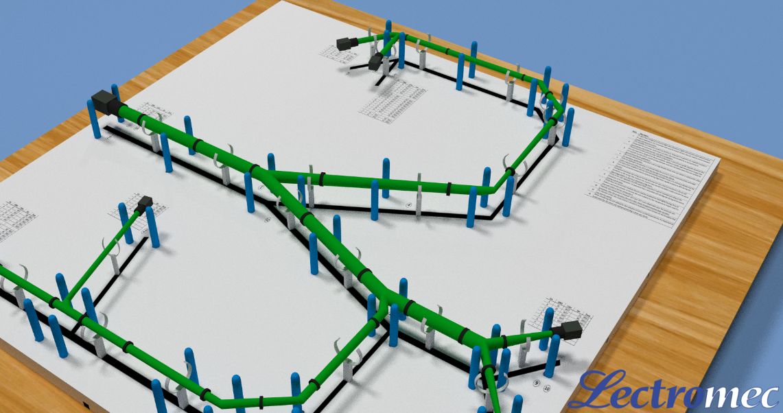
When some think of EWIS, they think of the wiring harnesses. But there is a lot more that falls into the boundaries of EWIS.
In response to this, the FAA cited the Lauda Air incident report. “Investigation of the accident disclosed that certain ‘‘hot-short’’ conditions involving the electrical system occurring during an auto-restow command, could potentially cause the DCV to momentarily move to the deploy position.”
As such, the FAA views the wiring within the engines, nacelles, and APU is part of the EWIS and is subject to the same requirements as other areas of the aircraft where EWIS is installed.
AS50881
Other industry documents follow similar thoughts when considering the aircraft EWIS boundaries. The SAE document on EWIS installation, AS50881, pertains to, “wiring inside of airborne electronic equipment, but shall apply to wiring externally attached to such equipment.”
Reviewing the AS 50881 as a whole suggests that the standard believes in the same physical/logical EWIS boundaries as identified in the FAA’s guidance and regulatory requirements. The AS 50881 specifically states that wiring stops at LRUs and there are several sections that referred to the wiring attached to or routed near nacelles, engines, and APUs.
Implications
The fact is, nearly all parts of the aircraft where wiring is routed from one piece of equipment to another require some level of EWIS evaluation. This means, until wireless power transmission becomes viable, the EWIS will need to be assessed for every system. Every LRU added to a vehicle, every additional antenna, every rework of the in-flight entertainment (IFE) system, will require an EWIS impact analysis.
The EWIS analysis depth and breadth will vary from project to project, just like any other system assessment. In some cases, the impact may require unpopular changes to be made. This may require additional routing or more complicated routing in order to avoid and maintain separation distance from critical systems. The analysis might point to additional secondary harness protection to protect from maintenance actions. The number of factors it goes into a properly designed and safe EWIS is rather extensive (the AS 50881 is a 124-page document for a reason).
Final Review
If wiring is outside of a piece of equipment, then there is a strong chance it is part of an aircraft’s electrical wiring interconnect system. As with every other part of aircraft design, overhaul, and maintenance, how each EWIS component is selected, designed, installed, maintained must be documented. For those seeking FAA certification, adherence to best practices established by the industry and following the latest EWIS regulations is the only way to achieve compliance.
For those looking for EWIS compliance or certification assistance, contact Lectromec. Our experience, lab capabilities, and software tools are a great resource for anyone looking to expedite their EWIS certification.

Michael Traskos
President, Lectromec
michael.traskos@lectromec.comMichael has been involved in wire degradation and failure assessments for more than a decade. He has worked on dozens of projects assessing the reliability and qualification of EWIS components. Michael is an FAA DER with a delegated authority covering EWIS certification and the chairman of the SAE AE-8A EWIS installation committee.