Key Takeaways
- A wire/cable’s temperature rating is typically verified via accelerated thermal aging.
- Samples are placed into high temperature ovens exceeding the expected maximum temperature rating.
- While this method is used in most of the wire/cable industry, there are weaknesses with this assessment method.
How many wire types/constructions exist? A search of the SAE website finds thousands of wire/cable standards (typically aerospace and automotive), and this does not cover the design variations within each of these standards. As one would expect, wire and cable constructions change based upon the application. A wire for an automotive application will have different performance characteristics than a wire designed for in-home use.
While there is a wide range of products from which to choose, across many of these specifications there is a common element: maximum temperature rating. Here, we walk through a couple of the methods for assessing a wire/cable’s maximum temperature rating. At the end of this article, we delve into weaknesses of this assessment method and elements that should be considered when selecting a wire for your high temperature application.
Summary of Terms
As a starting point for this review, it is important to understand the terms used:
– Accelerated Aging: Accelerated aging relies on the idea that materials or components can be subjected to stresses exceeding their expected use to estimate product life. This could be mechanical (such as vibration, shock, etc.), chemical (exposure to concentrated fluids), or thermal (very high or very low temperatures).
– Temperature index: Temperature index is a term used across industries to define the thermal capability of the insulation. To put this another way, it is the maximum operational temperature for the insulation (note that the conductor may have a different maximum temperature). For the IEC60172 standard, the maximum-lifetime at maximum-temperature is 20,000 hours; in comparison, ASTM D3032 leaves this limit open to the user.
– Enameled wires: Enameled wires are those wires with a very thin layer of insulation. These wires are often used in winding wire applications.
– Winding Wires: Wires used for winding applications (e.g. inductors, electric motors, etc.) require tight packing to minimize air gaps (leading to partial discharge/corona) and to maximize performance. Winding wires is the term used to describe those wires used in these applications.
Thermal Aging
Two common methods for determining a wire/cable’s maximum temperature rating are the IEC60172 and the ASTM D3032 Method 14. The IEC60172 standard is intended for the evaluation of the temperature index of enameled and tape wrapped winding wires whereas the ASTM method is for general hookup wire. These two methods use accelerated aging to generate data for determining the maximum usable temperature.

Depending on the type of wire, the IEC 60172 test method may call for the wires to be kept straight or twisted upon itself (The color difference in the image is only for illustration purposes).
Since it is impractical to place a set of specimens into an oven for 20k hours (2.3 years) to verify the maximum rated temperature, other techniques are necessary to generate data in a timelier manner. Thermal index testing seeks to accelerate the aging through an established test plan. The data is then used to extrapolate performance at lower temperatures.
At a basic level, this test thermally stresses the material to failure. In that way, it is no different from many other material or component evaluation tests that stress the component to failure.
The Setup
The IEC60172 test relies on three main activities to stress the wire: temperature exposure, mechanical stress, and high voltage exposure.
- Wire setup: In this test, ten to twenty wires are prepared according to one of two methods – either the samples are spiral wrapped together (think double helix), or shaped and tied together with lacing tape with the final specimen length of approximately 10-12 inches. The method for preparing the specimen is insulation construction dependent.
- Elevated temperature exposure: The specimens are then attached to fixture and placed into a high temperature oven. The duration in the oven is dependent upon a combination of factors that include the expected material temperature rating and the test temperature. The IEC 60172 provides suggested oven exposure duration/temperatures based on the expected maximum rated temperature.
- Mechanical stress: Depending on the test method, after the high temperature exposure interval, the samples are placed on mandrels and subjected to a bend test.
- High voltage exposure: In this test, the center sections of the wires are submerged in water, a high voltage is placed on the conductor, and a ground return is placed in the water bath (dielectric voltage withstand test). Any sample with an insulation breach (as identified with a high current) is removed from the specimen group; those samples without an insulation breach are returned to the test fixture and subjected to another oven-bend-voltage cycle. This process is repeated until all of the samples have failed.
Selecting Temperature
Even with temperatures exceeding the expected temperature rating of the wire, the test performance may take several months. When performing these tests, the temperature selection is coordinated with the client based on material performance, available time, and budget. Excessive high temperatures may cause failure modes outside of standard performance criteria (discussed further later in this article).
The Arrhenius equation suggests that every 10oC increase in temperature doubles chemical reaction speed and reduces component life by half. For wire/cable temperature ratings seeking qualification at 100k hours, this suggests an approximate life expectancy of 1560 hours at 260oC. The European wire specification DN2267 requires a 100k hour rating at 200oC and 10k hours at 260oC.
Data Evaluation
The time to failure of a specimen group at a given temperature is based on the median or logarithmic mean value. Other standards that consider the thermal index of wires cite the logarithmic mean value as the preferred method.
A single set of data points at a given temperature is inconsequential for predicting long-term thermal performance. To provide a meaningful prediction, at least three different temperatures must be tested. Because of this requirement, thermal index testing can take several months to complete (likely a minimum of 6 months).
As an example: We have a wire with an expected thermal index of about 180oC. Using this as a starting point, three temperatures are selected from the IEC standard for evaluation: 220oC, 240oC, and 260oC. After running the sample through the thermal-exposure and WDVW test cycles, we get the following data (the data in the table shows the number of insulation failures recorded at the end of each cycle).
|
Cycle |
220oC |
240oC |
260oC |
|
1 |
0 |
0 |
0 |
|
2 |
0 |
0 |
0 |
|
3 |
0 |
0 |
0 |
|
4 |
0 |
0 |
0 |
|
5 |
0 |
0 |
0 |
|
6 |
0 |
0 |
0 |
|
7 |
0 |
0 |
0 |
|
8 |
0 |
1 |
0 |
|
9 |
1 |
0 |
0 |
|
10 |
2 |
1 |
3 |
|
11 |
2 |
5 |
4 |
|
12 |
4 |
3 |
5 |
|
13 |
4 |
3 |
6 |
|
14 |
5 |
4 |
2 |
|
15 |
2 |
2 |
0 |
|
16 |
0 |
1 |
0 |
Taking this failure data to determine the logarithmic mean time to failure (MTTF), it is possible to calculate the trend line, then extrapolate the graph backwards until the 20k MTTF value is reached. This then provides a suggested thermal index of the insulation of 182oC.
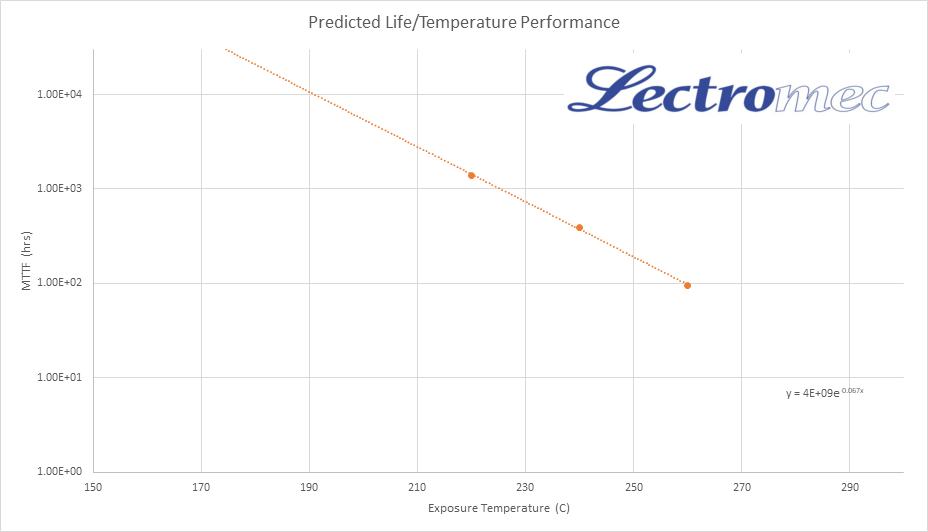
Accelerated aging can be used determine the reliable service life at maximum temperature under certain conditions. Here the 20k hour service life predicted to be about 182oC.
Weaknesses of This Method
This method has been, and continues to be used, across several industries. There are a couple factors that should be considered before employing this method to determine a wire/cable’s maximum rated temperature.
- Performance limitation: This means for determining the maximum temperature does not consider dynamic stresses. Research has shown that insulation mechanical strength will significantly reduce in high temperature applications. For some wire insulation materials, their mechanical performance at elevated temperature is very poor and can only survive the most superficial mechanical stress.
- Unexpected Failure Mode: As identified earlier, using elevated temperature to accelerate aging can cause failure modes to appear that are unlikely to be experienced during normal use. This is like using a sledgehammer to determine the dent resistance of a sheet of metal; if the service life of the metal will only encounter soccer balls, the sledgehammer is not representative method to stress the metal.
- Time: Depending on how high a temperature is used, this test method may take two months or it may take a year. If thermal index test is needed, it should be planned for early in the product development cycle.
Interested in Applying This?
The thermal index test method is a common method to determine the long-term life of a wire/cable. For winding wire, the standard is IEC60172; for aerospace and general hookup wire, the ASTM D3032 and AS4373 follow a very similar process.
If you have the need to determine the thermal index of your wire/cables, contact Lectromec. We are ready to help.

Michael Traskos
President, Lectromec
michael.traskos@lectromec.comMichael has been involved in wire degradation and failure assessments for more than a decade. He has worked on dozens of projects assessing the reliability and qualification of EWIS components. Michael is an FAA DER with a delegated authority covering EWIS certification and the chairman of the SAE AE-8A EWIS installation committee.