Key Takeaways
- While the idea of a fully wireless aircraft may seem appealing from a weight savings perspective, there are several aircraft electrical needs that simply cannot be met with current wireless technology.
- Many of the most safety-critical systems on aircraft require multiple levels of redundancy which simply cannot be replicated or sufficiently matched by wireless systems.
- The introduction of extensive wireless functions also introduces a greater potential for EMI (Electromagnetic Interference).
Introduction
Miles of copper wire connect sensors, controls, and systems which add thousands of pounds to an aircraft, thus there has been a continuous drive for the use of lighter aluminum conductors, and maybe at some point, carbon nanotubes. Wireless Avionics Intra-Communications (WAIC) has emerged as a concept to “cut the cord” for certain intra-aircraft links. By using radio links between onboard components, WAIC could reduce wiring weight and simplify installation. Idealized models suggest that perhaps 20–30% of an aircraft’s wiring (especially for non-critical data communications) might be replaced by wireless systems. Beyond weight savings, wireless sensors offer easier reconfiguration and the ability to monitor hard-to-wire parts (like rotating or moving components). The background of this idea, the design approach, and its limitations are discussed in this article.
Overview
WAIC is defined as radiocommunication between two or more points on a single aircraft. It is a closed, exclusive network for safety-related avionics and is separated from other RF users such as Wi-Fi and air-to-ground communications. The International Telecommunication Union (ITU) allocated a protected worldwide frequency band 4200–4400 MHz for WAIC at WRC-15 (World Radiocommunications Conference – 2015). This frequency band is also used by radio altimeters, so to avoid conflicts, the WAIC transmitters must be ultra-low power and designed not to interfere with these critical sensors.
Accordingly, WAIC devices must operate at short range under 100 m, which is not an issue for most aircraft. As stated previously, the WAIC devices must be low power, between 10 mW for low-rate sensors and up to 50 mW for higher-rate nodes. Like all systems on aircraft, coordination is necessary, and international groups like RTCA SC-236 and EUROCAE WG-96 are developing minimum operational performance standards to ensure WAIC systems can safely coexist with existing avionics.
Expected Functions
Industry studies and the WAIC working group have identified candidate systems such as primary sensors and monitoring systems. Examples include smoke detectors, fuel tank sensors, landing gear monitors, proximity sensors for doors and cargo, cabin climate, structural health monitoring nodes, and even certain non-critical feedback signals from engines or flight control surfaces. The list are those items that are non-flight critical systems but are still important functions for aircraft operations and safety. The obvious goal is to reduce the wiring to improve fuel efficiency and reduce assembly/maintenance costs. The argument is that fewer wires would mean fewer failure points (no broken wire or corroded connector issues) and easier upgrades by simply adding wireless sensors where needed, but power would still be needed for these components.
While Lectromec’s articles focus on EWIS technologies, even the staunch supporter of WAIC must admit that it is no panacea. There will always remain crucial aircraft systems that cannot realistically be made wireless with today’s technology or safety criteria. In the weight-critical and safety-critical overlap that aerospace sits in, reliability and performance are top priority.
In the following sections, we examine the major categories of systems that will continue to rely on wired connections: (1) power distribution, (2) critical control systems, (3) high-data-rate links, (4) EMI-sensitive circuits, and other considerations. Understanding these boundaries is essential for a realistic adoption of WAIC – one that enhances aircraft performance without compromising safety or functionality.
Power Distribution: Wires Still Required for Energy Transfer
One fundamental limitation of going “all wireless” in an aircraft is power delivery. Electrical power cannot be sent wirelessly throughout an airliner in any practical way – at least not with the efficiencies, distances, and power levels required. While small-scale wireless charging (inductive pads, etc.) exist for consumer devices, scaling technology to support LRUs or actuators around a large airframe is infeasible. The vast majority of onboard systems will continue to receive power through hardwired electrical cables. Even a battery-powered wireless sensor node must ultimately get its battery charged or replaced, which in effect shifts the problem rather than eliminates the wire.
On a traditional wired system, a group of cables are bundled together to carry power and data/signals to a device, or in PoDL architectures, both may be in the same cable. In a wireless setup, the data may be transmitted wirelessly, but each remote device still needs a source of power – typically a battery or a local connection to power. This introduces several issues: added weight (batteries add mass, negating some of the weight savings of removing wires) and maintenance burden (batteries need regular replacement and/or monitoring). Wireless sensor networks can reduce structural weight, adding batteries will increase maintenance activities. In fact, studies have found that using wireless sensors ubiquitously for structural monitoring could be impractical largely because the sheer number of batteries required would negatively impact reliability and negate any cable weight savings. Long-life power is a major challenge – ideally, such wireless devices would need to last for years without intervention, something that is difficult to achieve with modern battery technology.
Safety-Critical Systems: Reliability and Control Cannot Go Wireless
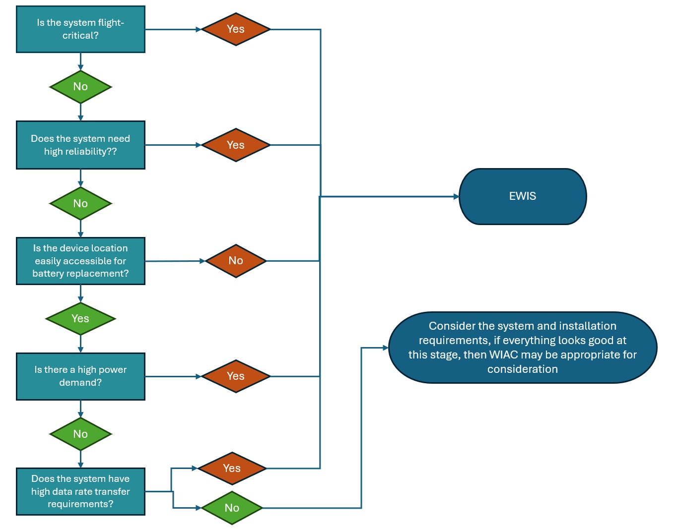
Guidance for consideration of wireless system integration on aircraft.
Perhaps the most obvious category of systems that will remain wired are those classified as safety-critical, where failure or loss of signal could immediately endanger the aircraft and the flight control system. Modern airliners use fly-by-wire controls that send electrical signals to actuators that move the control surfaces. These fly-by-wire networks are designed with robust redundancy – typically triple or quadruple-redundant wiring and computers so that no single failure can sever the link between pilot and aircraft. In such a design, replacing even one of those physical wires with a wireless link would introduce an unreliability that is unacceptable under current safety standards.
Active transmitters and receivers can fail or lose reception due to interference or obstacles. In contrast, a passive shielded wire, properly routed, is essentially immune to electromagnetic noise and has no “range” issues (assuming signal attenuation is accounted for with the cable selection). Thus, for a flight-critical connection, OEMs tend to focus on adding more wires rather than risking a drop in reliability. Weight savings is simply not a consideration when the integrity of the flight controls is on the line.
Beyond flight controls, other Category A (most critical) systems include things like engine full-authority digital engine control (FADEC) command links, primary navigation sensor feeds, and communications between essential avionics. These also demand essentially 100% availability. It is not just a theoretical concern: one can imagine scenarios that make wireless links risky – e.g. strong external radio interference, intentional jamming, or even something as mundane as a blown fuse in a wireless transceiver could sever a vital control channel. With wires, especially multiple redundant wires, the failure modes are well understood and mitigated (physical separation, shielding, etc., per regulations).
With wireless systems, common-mode failures are harder to eliminate. For instance, if all wireless control links share the same frequency band, a single source of interference could conceivably affect them all simultaneously. No commercial airliner or certified aircraft today relies on wireless for real-time flight control actuation or critical sensor data, and regulatory agencies like FAA/EASA would require overwhelming proof of equal reliability before ever allowing it.
High Data-Rate Networks: Bandwidth and Latency Needs Favor Wires
Another domain where wires maintain an edge is high-bandwidth and real-time data networks. Aircraft are increasingly digital, with high-speed data buses carrying video, audio, and large volumes of sensor data. Current examples include avionics Ethernet backbones like AFDX (Avionics Full-Duplex Switched Ethernet, used in Airbus A380/A350, Boeing 787, etc.) running at 100 Mbps or more, high-speed ARINC 818 fiber optic links for high-resolution video, and Gigabit links for flight test instrumentation or in-flight entertainment. These wired networks can transport megabits to gigabits per second of data with low latency and are designed for deterministic performance (packets arrive on time, in sequence, with minimal loss).
In contrast, the current WAIC concepts are based on low-power wireless technologies closer to personal-area networks. For instance, many WAIC studies leverage IEEE 802.15.4-derived protocols, which typically offer data rates up to around 250 kbps per channel under ideal conditions. Even with more advanced modulation or channel bonding, the wireless throughput available for WAIC is orders of magnitude less than what modern wired avionics networks deliver. Moreover, wireless links often have higher latency and non-deterministic behavior – interference or contention can cause variable delays. A WAIC study acknowledged that while wireless is useful for many sensor needs, its “non-deterministic behavior and sensitivity to interference and jamming” mean these features “may not be sufficient to provide the real hard telecommunication required by aircraft applications [Link].” In other words, for the most timing-critical, data-heavy communications, wireless still falls short.
EMI-Sensitive Equipment: Managing Electromagnetic Interference
Electromagnetic interference (EMI) is always a concern in aircraft and EWIS design. Anyone who has gone through the DO-160 EMI testing requirements for components knows the complexity of aerospace component EMC verification tests. Avionics must operate amidst electromagnetic activity ranging from onboard sources (radios, transmitters, switching power supplies) to external sources (weather radars, lightning, and cosmic radiation). In this environment, adding new wireless transmitters (as WAIC does) must be done very carefully to avoid disrupting sensitive circuits. Certain systems are extremely EMI-sensitive thus the safest course is to keep them wired and physically separated from RF emitters.
Therefore, we can expect that EMI-critical systems will retain wired connections or heavily shielded means of communication. If a WAIC device is used, it might be in a shielded enclosure or turned off when not needed, etc., to mitigate interference. It is noteworthy that WAIC components will have to pass DO-160 radiated emissions tests – which limit the stray emissions that could affect other systems. Achieving those limits while transmitting RF is tricky; it means very controlled antenna designs and power levels. In summary, for avionics where signal purity is paramount (navigation, communication, certain sensors), designers will avoid introducing any unnecessary antennas. Wires, in these cases, remain the quieter and more secure option.
Conclusion
The advent of WAIC does herald a new era for aircraft systems, one where certain electrical connections can be made without physical wires. This offers exciting possibilities: easier installation of sensors in hard-to-reach spots and the possibility to reduce weight leading to fuel savings. As the technology and standards mature, OEMs will likely see more onboard systems take advantage of wireless intra-aircraft communications. Non-critical and auxiliary systems will go wireless first, while the critical systems will remain wired.
In practice, future aircraft will probably employ a hybrid network architecture. Heavy gauge power wires, high-speed data buses, and critical command wires will form the backbone (ensuring power and critical data get through under all conditions). The aircraft traditional physical EWIS will overlap with a mesh of WAIC nodes. This hybrid approach is hinted at by ongoing industry efforts – for example, using power-line communication or wireless only for secondary channels, and maintaining wired failsafes.
For the time being, those looking to support their EWIS component and system level testing and engineering support, contact Lectromec. We are ready to continue to support the industry as long as there is still at least one wire on aircraft.

Michael Traskos
President, Lectromec
michael.traskos@lectromec.comMichael has been involved in the field of EWIS for more than two decades and has worked on a wide range of projects from basic component testing, aircraft certification, and remaining service life assessments. Michael is an FAA DER with a delegated authority covering EWIS certification, the former chairman of the SAE AE-8A EWIS installation committee, and current vice chairman of the SAE AE-8D Wire and Cable standards committee.