View Latest Blog Entries
Close
Categories
Testing & Assessment Certification Standard & Regulation Aging Wires & Systems Maintenance & Sustainment Management Conference & Report Protection & Prevention Research Miscellaneous Arcing
Popular Tags
Visual Inspection High Voltage AS50881 MIL-HDBK MIL-HDBK-525 FAR AS4373 Electromagnetic Interference (EMI) Maintenance FAR 25.1707 Wire System Arcing Damage
All Tags in Alphabetical Order
2021 25.1701 25.1703 abrasion AC 33.4-3 AC 43 Accelerated Aging ADMT Aging Systems AIR6808 AIR7502 Aircraft Power System aircraft safety Aircraft Service Life Extension Program (SLEP) altitude arc damage Arc Damage Modeling Tool Arc Fault (AF) Arc Fault Circuit Breaker (AFCB) Arc Track Resistance Arcing Arcing Damage AS22759 AS22759/87 AS23053 AS29606 AS4373 AS4373 Method 704 AS50881 AS5692 AS6019 AS6324 AS81824 AS83519 AS85049 AS85485 AS85485 Wire Standard ASTM B355 ASTM B470 ASTM D150 ASTM D2671 ASTM D8355 ASTM D876 ASTM F2639 ASTM F2696 ASTM F2799 ASTM F3230 ASTM F3309 ATSRAC Attenuation Automated Wire Testing System (AWTS) Automotive Avionics backshell batteries bend radius Bent Pin Analysis Best of Lectromec Best Practice bonding Cable Cable Bend cable testing Carbon Nanotube (CNT) Certification cfr 25.1717 Chafing Chemical Testing Circuit Breaker circuit design Circuit Protection cleaning clearance Coaxial cable cold bend collision comparative analysis Compliance Component Selection Condition Based Maintenance Conductor Conductor Testing conductors conduit Connector Connector rating connector selection connector testing connectors contacts Corona Corrosion Corrosion Preventing Compound (CPC) corrosion prevention Cracking creepage D-sub data analysis data cables degradat Degradation Delamination Derating design safety development diagnostic Dielectric breakdown dielectric constant Dimensional Life disinfectant Distributed Power System DO-160 dry arc dynamic cut through E-CFR electric aircraft Electrical Aircraft Electrical Component Electrical Power Electrical Testing Electrified Vehicles Electromagnetic Interference (EMI) Electromagnetic Vulnerability (EMV) Electrostatic Discharge EMC EMF EN2235 EN3197 EN3475 EN6059 End of Service Life End of Year Energy Storage engines Environmental Environmental Cycling environmental stress ethernet eVTOL EWIS certification EWIS Component EWIS Design EWIS Failure EWIS sustainment EWIS Thermal Management EZAP FAA FAA AC 25.27 FAA AC 25.981-1C FAA Meeting failure conditions Failure Database Failure Modes and Effects Analysis (FMEA) FAQs FAR FAR 25.1703 FAR 25.1707 FAR 25.1709 Fault fault tree Fixturing Flammability fleet reliability Flex Testing fluid exposure Fluid Immersion Forced Hydrolysis fuel system fuel tank ignition Functional Hazard Assessment functional testing Fundamental Articles Fuse Future Tech galvanic corrosion Glycol Gold Gold plating Green Taxiing Grounding hand sanitizer handbook Harness Design harness protection hazard Hazard Analysis health monitoring heat shrink heat shrink tubing high current high Frequency high speed data cable High Voltage High Voltage Degradation HIRF History Hot Stamping Humidity Variation HV connector HV system ICAs IEC 60851 IEC60172 IEEE immersion insertion loss Inspection installation installation safety Instructions for Continued Airworthiness insulating material insulating tape Insulation insulation breakdown insulation resistance insulation testing interchangeability IPC-D-620 ISO 17025 Certified Lab ISO 9000 J1673 Kapton Laser Marking life limit life limited parts Life prediction life projection Lightning lightning protection liquid nitrogen lithium battery lunar Magnet wire maintainability Maintenance Maintenance costs Mandrel mean free path measurement mechanical stress Mechanical Testing MECSIP MIL-C-38999 MIL-C-85485 MIL-DTL-17 MIL-DTL-23053E MIL-DTL-3885G MIL-DTL-38999 MIL-E-25499 MIL-HDBK MIL-HDBK-1646 MIL-HDBK-217 MIL-HDBK-454 MIL-HDBK-516 MIL-HDBK-522 MIL-HDBK-525 MIL-HDBK-683 MIL-STD-1353 MIL-STD-1560 MIL-STD-1798 MIL-STD-464 MIL-T-7928 MIL-T-7928/5 MIL-T-81490 MIL-W-22759/87 MIL-W-5088 MIL–STD–5088 Military 5088 modeling moon MS3320 NASA NEMA27500 Nickel nickel plating No Fault Found OEM off gassing Outgassing Over current Overheating of Wire Harness Parallel Arcing part selection Partial Discharge partial discharge at altitude Performance physical hazard assessment Physical Testing polyamide polyimdie Polyimide-PTFE Power over Ethernet power system Power systems predictive maintenance Presentation Preventative Maintenance Program Probability of Failure Product Quality PTFE pull through Radiation Red Plague Corrosion Reduction of Hazardous Substances (RoHS) regulations relays Reliability Research Resistance Revision C Rewiring Project Risk Assessment S&T Meeting SAE SAE Committee Sanitizing Fluids Secondary Harness Protection separation Separation Requirements Series Arcing Service Life Extension Severe Wind and Moisture-Prone (SWAMP) Severity of Failure shelf life Shield Shielding Shrinkage signal signal cable Silver silver plated wire silver-plating skin depth skin effect Small aircraft smoke Solid State Circuit Breaker Space Certified Wires Splice standards Storage stored energy superconductor supportability Sustainment System Voltage Temperature Rating Temperature Variation Test methods Test Pricing Testing testing standard Thermal Circuit Breaker Thermal Endurance Thermal Index Thermal Runaway Thermal Shock Thermal Testing tin Tin plated conductors tin plating tin solder tin whiskering tin whiskers top 5 Transient Troubleshooting TWA800 UAVs UL94 USAF validation verification video Visual Inspection voltage voltage differential Voltage Tolerance volume resistivity vw-1 wet arc white paper whitelisting Winding wire Wire Ampacity Wire Bend Wire Certification Wire Comparison wire damage wire failure wire performance wire properties Wire System wire testing Wire Verification wiring components work unit code

Lectromec’s Testing Process

Testing & Assessment

Testing can be complex. From test identification, locking down on test parameters, sample preparation, accurate test performance, proper data analysis, and delivery of a final report, an error anywhere in the process can cause costly delays and spurious results. Using the correct laboratory for testing is undoubtedly important.

This article provides an overview of how testing comes into Lectromec’s lab, how the testing is performed, tracked, and what to expect from the final results.

ISO 17025 Sample Tracking
Keeping track of samples is key for smooth project flow. Lectromec’s receiving process ensures that the right work is done on the right samples.

Client Request and Purchase Order

Prior to any testing is performed, a project work or purchase order is created identifying the type of test methods to be performed as requested by and agreed upon with the client. After the purchase order for the work has been completed, work items associated with the samples created and added to Lectromec’s project tracking system. During this time, if any tests require clarification on test parameters (e.g. temperature, weight on sample during testing, etc.), these are communicated to the client and agreed upon prior to moving forward with testing.

For larger projects with multiple samples and/or a variety of test methods with specialized parameters, a project tracking matrix is reviewed with the client to ensure that all tests are performed to match the particular specifications of the client.

After the agreement is finalized and modifications to the work completed, the client works to supply the samples for testing to Lectromec’s lab for the next phase in the project.

Client Sample Receipt

When the client’s samples have arrived at Lectromec, they are added to Lectromec’s receiving queue. Here, each specimen in verified against the project work or purchase order to ensure the sample is allocated to the correct project and handled accordingly. Furthermore, a preliminary visual examination is performed on the samples to determine if any damage occurred during shipping. Any suspected damage is immediately report to the client.

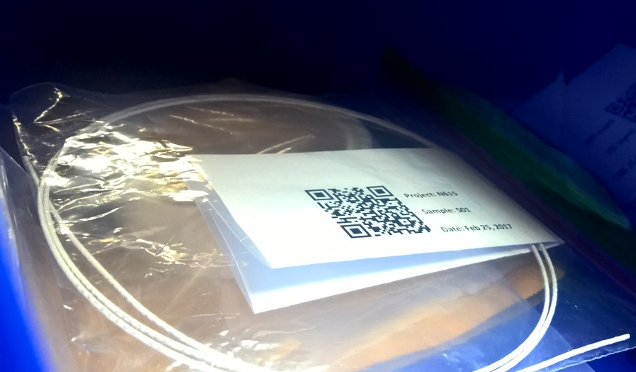
If no damage is identified, the sample is the entered into Lectromec’s project tracking system as a receivable, assigned a unique internal tracking number, and a unique identification or QR code is affixed to each sample. This provides a reliable means of tracking the sample throughout the project.

The samples are then placed into a climate controlled environment ready for the next phase.

Project Testing

The testing start date will vary depending on the particular test requested and the number of other projects ahead in the test queue. Lectromec continually strives for testing to be completed within three weeks after receiving the client’s samples but this may vary due to some tests that are designed to run until failure. As an example, the scrape abrasion test may take anywhere from 6 minutes to 6 days – and 10 trials are required by the test method.

When the samples are ready to be tested, Lectromec’s lab personnel assigned to perform the test select and verify the correct sample by scanning the QR code, remove the necessary quantity or length per the test method, and begin test preparation.

As an ISO 17025 certified lab, we care about the quality of all tests performed in our lab, therefore, tests are only performed by individuals that have been trained on the test method selected and have shown a high level of proficiency within the previous 12 months.

Each test station is paired with the tools necessary for test performance and most up-to-date instructions to ensure the test is performed according to specification. This means that there is never a question about how the test should be performed. As part of Lectromec’s continuous internal review process, whenever a new test variant is identified or needs clarification, the internal procedures are reviewed, and if necessary, updated.

Depending on the test being performed, the data may be recorded digitally or is converted after the test is complete.

For those interested, Lectromec can provide a live web feed or video to watch the testing be performed. Please note that this may be an additional cost for your project.

ISO 17025 Sample Tracking
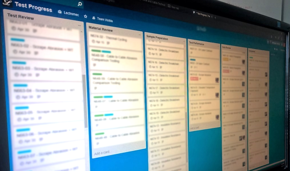
For years, Lectromec’s lab operated on a paper tracking system. Since moving to our digital tracking system, error rates have decreased, and throughput has increased. Also, each employee now has immediate and full visibility into the status of each project.

Reporting

Lectromec provides a detailed report for each of the tests that is performed. Typically, a client can expect the report will include many of the following:

  • Description of what is evaluated with the test method used,
  • Clearly identified parameters and margins of error on measurements,
  • Photos of the test setup,
  • Test results often with pre- and post-test photos (if applicable),
  • Data analysis, and
  • Comparison against a specification to identify if the component passed or failed the criteria.
    After the report is delivered, Lectromec schedules a final consultation to address any questions the client may have with the project results.

Summary

At Lectromec, we care about providing high quality results and transparency when handling client’s testing needs, which is why we integrated throughout our process ways to track and communicate project status to our clients. This ensures that each project is handled with the utmost care and that each client has opportunities to present questions at each phase of the project cycle. Contact Lectromec to find out more.

Michael Traskos

Michael Traskos

President, Lectromec

Michael has been involved in wire degradation and failure assessments for more than a decade. He has worked on dozens of projects assessing the reliability and qualification of EWIS components. In September 2014, Michael was appointed as an FAA DER with a delegated authority covering EWIS certification.