Key Takeaways
- Diversity in high-voltage systems raises the question of where and to what extent the responsibility of testing lies between the wire/cable manufacturer and the OEM.
- The aviation industry must consider whether arc track resistance should be evaluated at the component-level or at the system-level for high-voltage systems.
- Arc track resisting as we know it may be coming to an end as more HV systems with unique testing requirements lead the aviation industry moving forward.
Is it sufficient to verify individual components are safe for use or must there also be an assessment for safety at the system integration level? A gut reaction typically implies that a component must be deemed safe (and acceptable) before integration into the system, but what if the integration into the system makes its use safe? These are the questions that plague any engineer or system designer and are a fundamental challenge for those building an EWIS for a high voltage power system.
In Lectromec’s last article, basic component tests were considered for assessing high-voltage arc track resistance. While possible solutions were proposed, there were still gaps impeding full adoption. This article continues to explore potential solutions for assessing and quantifying arc track resistance for high voltage wires, albeit from the system integration, OEM, and regulator perspectives.
Specific Voltages – OEM Defined
Stepping back to voltage-specific testing for the particular application, one could expect limited performance testing to be done by wire/cable manufacturers. As there is no way for a wire/cable manufacturer to know or test for every power system type, the manufacturer may perform some preliminary tests or engineering evaluations to claim a certain voltage performance level (such as those in AIR 7502), but the particular arc track resistance requirements would be left to the aircraft OEM to substantiate for their particular power system. A parallel to this is seen with flex endurance testing; wire/cable manufacturers perform basic testing, but it is the responsibility of the system designer to validate the component for their application.
If this approach is taken, it puts the aircraft OEM back into the position of determining what test method is appropriate for their application, in particular, whether the OEM views arc track resistance as a component-level test or system-level test. If the arc track resistance is a component-level test, then generalized test methods can be used (box 4 or 5).
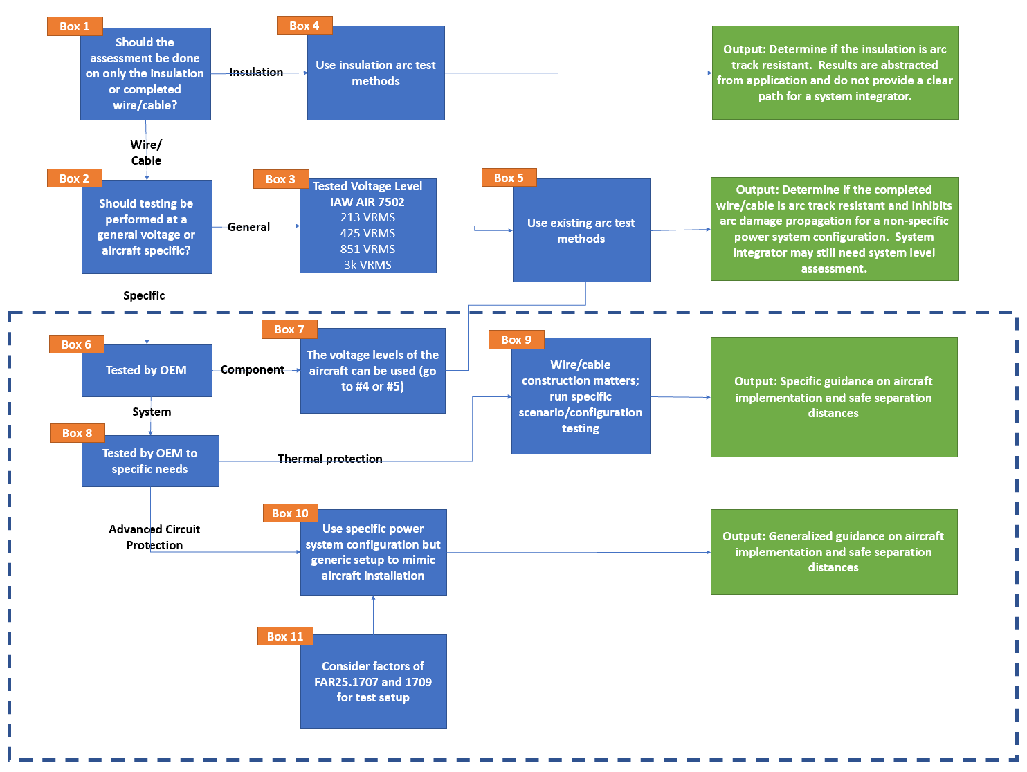
This flow chart is one of the many possible logical flows in identifying arc track resistance considerations for high voltage systems.
OEM and System Level Testing
If arc track resistance is determined to be a system-level test (box 8), then other factors such as the power system, specific circuit protection, and other aircraft OEM design factors should be introduced. This then changes the foundation of the testing from a material/component test to one that aligns more with the fielded system. The power system and circuit protection are aircraft-specific and have a significant impact on the test setup and results. If the power system uses slow responding circuit protection, such as thermal circuit breakers or fuses, the particular wire/cable configuration (insulation, shielding, etc.) has an appreciable impact.
However, if the power system uses advanced circuit protection technologies which may respond in milliseconds (box 10), should this not be factored in when determining the failed wire impact? The approach of box 10 pushes one to consider if the arc track resistance of these components in high voltage and high energy systems really matters.
At some point it must be accepted that the insulating materials that are used for aircraft wiring will be incapable of preventing cascading damage within wire harnesses unless the insulation becomes extremely thick and unusable for aerospace applications (assuming slow responding circuit protection scenarios). Taking the position that wires will have arcing failure conditions, (as is required from the perspective of FAR 25.1709) a different approach to the problem must be considered.
In accordance with AC25.1701-1, it must be assumed that any section of wire harness may be lost/damaged and the consequences must be assessed from both a physical and functional impact. How that failure occurs is left open but for this discussion, the assumption is that the wire harness is damaged through an electrical arcing event. One cannot assume that the wire harness will be set in any particular configuration limiting the cascading damage. Taking this approach, the materials of the wire harness have less of an impact, and an assessment of the worst-case arcing event that can occur given the available current, voltage, and circuit protection is required.
The aircraft OEM then needs to ensure that those aircraft components near the arcing wires are a sufficient distance away to prevent cascading damage and ensure that the loss of the single wire harness does not result in a hazardous or catastrophic failure event. This is something that should already be done for every aircraft that is EWIS compliant and certified.
Direct contact between a wire conductor and a conductive aircraft component is a relatively simple failure mode to quantify. When this test is done considering system separation, factors such as ambient air pressure, air flow, enclosure size, and others creep into the equation.
Conclusion
This thought exercise for EWIS wire arc track resistance requirements suggests that the era of performing arc track resistance for wiring distributed power through an aircraft may be coming to an end. From a wire/cable producer standpoint, arc track resistance testing requirements for high voltage systems will become so fractured that it will be impossible to ensure arc track resistance for a generalized application as has been done for low voltage systems (e.g., 115VAC power systems).
From an OEM perspective, focusing on the aircraft requirements seems more practical than searching for components that may be able to achieve the same arc damage resistance properties that have been used for part selection for the last four decades.
However the next generation of wire and cable are tested for arc track performance, Lectromec’s ISO 17025 accredited lab will be here and ready to help.

Michael Traskos
President, Lectromec
michael.traskos@lectromec.comMichael has been involved in wire degradation and failure assessments for more than a decade. He has worked on dozens of projects assessing the reliability and qualification of EWIS components. Michael is an FAA DER with a delegated authority covering EWIS certification and the chairman of the SAE AE-8A EWIS installation committee.