
Use of MIL-T-81490 cable in place of a MIL-DTL-17 cable
The transmission of electrical energy is, surprisingly, not a trivial task. At low frequencies and low power, a very primitive wire construction is possible and can be successful for extended applications. As frequencies increase, the need for focused attention becomes ever more apparent.
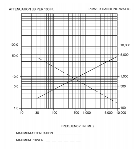
A common ‘go-to’ cable for RF applications is the MIL-DTL-17 (sometimes MIL-C-17) cable. Many of the MIL-DTL-17 cables are rated to 1 GHz, some to 12.4 GHz (like M17/128), and only a couple at 20GHz (e.g. M17/130 and M17/133 – a word of caution with the /130 and /133 constructions: these are unjacketed cables with an exposed external conductor/shield). There is the M17/205 construction that is spec’d for up to 50GHz, but that comes with a caveat: attenuation. The accompanying figure shows the attenuation per 100ft of M17/205 cable; while the attenuation does rise quickly with higher frequencies, the specification does not provide any attenuation limits beyond 10 GHz.
If someone is looking for that high-frequency performance, what options are there? One option is the MIL-T-81490 cable.
What are MIL-T-81490 Cables?
The MIL-T-81490 cables are specifically designed transmission line cables for aircraft systems (a transmission line in this case refers to cables designed for RF/microwave applications that must account for the properties of the propagated signal). Specifically, these cables are for applications that need to transmit with high fidelity high-frequency signals.
Construction of a MIL-T-81490 Cable
The MIL-T-81490 is a performance specification, not a detailed specification. For those that have not enjoyed years of standards, this means that elements of the cable’s construction are left to the manufacturer, but the cable must meet the minimum performance requirements outlined in the performance standard. What this means to the end user is that there can be significant performance variations between manufacturers.
First, there are three cable classes:
- Class 1: Flexible – to be used for installations where bending is required to facilitate running long lengths, where attachment to shock mounted equipment is required, and where large angular displacements are encountered during service and maintenance.
- Class 2: Semiflexible – to be used for installations where bending or forming is required to facilitate running long lengths, but where attachment to shock-mounted equipment is not required. This cable class is not intended for applications requiring continuous in-service flexing.
- Class 3: Rigid – to be used in installations where bending is not needed. These cables are formed during manufacturing and cannot bend without potential damage.
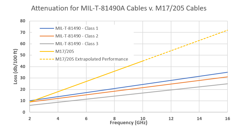
The more rigid structures offer better attenuation performance. The attenuation performance between the three cable types is shown in the accompanying figure. Each of these construction classes have better attenuation performance in comparison to the afore mentioned MIL17/205 cable type.
From a construction perspective, the MIL-T-81490 cable will consist of the following construction (inside out):
- Single core conductor usually plated with silver
- Dielectric material, typically of some PTFE base
- Shielding
- Jacket
A straight comparison between a MIL-T-81490 cable and most MIL-C-17 cable constructions finds very little difference. The difference comes down to the performance requirements.
Where Would you use a MIL-T-81490 Style Cable?
As mentioned earlier, MIL-T-81490 cables are primarily for high-frequency applications. In addition to the flexibility classes, there are two types of MIL-T-81490 cable: Type I is for use in the range of 2.0 – 8.0 GHz, and Type II is designed to extend that range up to 16.0 GHz. Because of these high frequencies, they are often part of navigation and communications systems, as well as any high-data rate application.
Obviously, one of the requirements for a cable to be considered viable is a low signal attenuation.
Insertion Loss
With high frequency applications, insertion loss is often a key parameter. Simply put, insertion loss is a ratio of the signal on a cable or circuit. To get into the weeds, insertion loss is defined mathematically as
IL(dB) = 10 log10 Pt/Pr
Where Pt is the transmitted power and Pr is the received power. Ideally, the transmitted power equals the received power and the insertion loss is equal to zero. However, practical factors, such as reflected losses at connectors or splices, imperfect dielectric materials (the insulation behavior), and the resistance of the signal carrier (copper conductor) reduce the total power received at the end of the circuit.
To improve (reduce) the reflected losses at connectors, matched impedance connectors, affixed with the correct tools, are needed. For the dielectric materials, materials research is an ongoing effort to improve the electrical, mechanical, and thermal properties and there is a balance to improving one property without diminishing the performance in others. The final area to reduce insertion loss is on the conductor; perhaps the easiest means of doing this is limit the mechanical stresses (i.e. tight bends) and repeat flexing.
Testing and Evaluation
The test and evaluation of the MIL-T-81490 cable looks at a variety of electrical performance tests (voltage standing wave ratio (VSWR), impedance, velocity of propagation, and RF leakage. Beyond the electrical, chemical, mechanical, and thermal tests which are typically used. Those tests that must be considered for first article inspection include:
- Voltage standing wave ratio
- Impedance
- Velocity of Propagation
- RF leakage
- Temperature
- Altitude
- Thermal Shock
- Vibration
- Power Handling Capability
- Impact Shock
- Flexure at -20, +25, and +60C
- Torque
- Tensile Load
- Concentrated Load
- Abrasion
- Chemical Resistance
- Explosive Atmosphere
- Humidity
- Salt Fog
- High Potential Withstanding Voltage
Conclusion
MIL-T-81490 cables are ideally suited for high-frequency applications seeking greater performance than available from MIL-C-17 cables. Because these cables are designed for aerospace applications, those cables meeting the performance requirements are aircraft ready.
For additional information about MIL-T-81490 cables and their use and application, WL Gore recently had a webinar on this topic. For those looking for testing, Lectromec’s ISO 17025 accredited lab is always ready to help.