
Solder Sleeves and Splicing in Shields
Shielded cables are necessary. They provide necessary EMI protection to ensure signal fidelity, and in some cables, such as coaxial cables, the shield is integral for signal transmission. Trying to use only non-shielded cables in any modern design would encounter such a significant impact on performance, it may not be possible except for a limited number of applications.
Because of this need for shielded cables, there is a wide range of components and supporting technologies to ensure proper use and reliable transmission of data. One of these technologies is a device to help with shield termination. Here, we review the need, use, and installation of solder sleeves.
Basics
If the cable’s shield were simply cut back and not terminated, this would leave a gap in the EMI protection creating an opportunity for electromagnetic noise to disrupt the signal integrity. Maintaining a continuous shield around the component conductors reduces the potential for EMI.
As a shielded cable arrive at connectors, if the connector is not designed for the termination of only that cable, it becomes vital for multiple cables to share the shielding to the connector shell. The shield termination at the connector becomes more complicated as the number of cables into a single connector increases (trying to properly terminate 10 shields at a single connector is not a trivial task). Solder sleeve products are designed to address the splicing and termination needs of shielded cables.
Installation
For installation, cable jacket is first stripped back to expose the shield. The length of this jacket removal is application dependent, but should be trimmed back enough that the shield and solder splice will not impact inserting component wires into the connector (this will likely be 1 – 5 inches depending on the number of wires into the connector and the connector size). The cable’s shield is then trimmed back away from the exposed cable end such that only a short segment of the shield remains exposed. The length of exposed shield will vary based on the cable size and solder sleeve combination and will range from 35 mils – 300 mils.
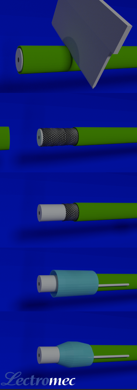
The solder sleeve is then installed over the exposed jacket and shield. Here is where the magic of the solder sleeve comes in. The solder sleeve device itself is a heat-shrinkable thermoplastic sleeve that contains fluxed solder. When heated, the thermoplastic sealing ring at both ends of the splice contracts to provide an environmental seal. Furthermore, the thermoplastic sealing rings also act as strain relief on the solder sleeve – shield connection point by damping the impact of any cable flexing.
With further heating of the solder sleeve, the solder in the solder sleeve melts creating a bond with the cable shield. If the solder sleeve has a ground wire, the shield is now electrically bonded with the ground wire that can now be terminated to the connector backshell.
Types
There are several types of splices that fall under the AS83519 standard for heat-shrinkable solder type shield terminations. These include:
- /1 that are supplied without a ground lead. This is so a solder sleeve can then have a ground wire added during installation. This device is classified as environmentally resistant. These also have a thermal indicator for indicating if sufficient heat has been applied to the solder-sleeve for the solder to wet and hopefully make a good connection with the ground wire.
- /2 These are similar to the /1 type but they are supplied with a ground lead.
- /3 These solder sleeves are supplied with a ground lead that is a shield braid. The shield braid enables improved termination in shielded harness applications. Whereas the ground wire from the /2 construction could be terminated in a connector contact, the shield braid is not intended for termination in contacts.
- /4 These solder sleeves are designed to terminate multiconductor cables. The solder sleeve has multiple holes, one for each of the cable’s component wires. A nice feature of these solder sleeves is that not every hole has to be filled; when heat is applied, the thermoplastic will seal any unused hole.
- /5 These are like the /2 but are ROHS compliant.
Testing
There are several tests that are defined in the AS8319 standard and may be employed as part of the solder sleeve’s qualification and quality assurance. These include:
- Recovery of the Thermoplastic – verify that thermoplastic property contacts with the application of heat.
- Longitudinal Change – verify the solder sleeve length does not change after the application of heat.
- Copper Mirror Corrosion- verify the solder sleeve does not cause corrosion.
- Voltage Drop – verify the millivolt drop across the sample is low.
- Insulation Resistance – verify the solder sleeve’s thermoplastic seal.
- Dielectric Withstand Voltage - verify the solder sleeve’s thermoplastic seal.
- Tensile Strength – verify the quality of the solder sleeve – shield connection.
- Altitude Immersion – verify performance under vacuum conditions.
- Temperature Cycling – verify performance under thermal cycling conditions.
- Moisture Resistance – verify performance when exposed to humid conditions.
- Fluid Immersion – verify performance after exposure to common aerospace fluids.
- Heat Aging – verify performance after high temperature exposure.
- Flammability – verify meets aerospace flammability requirements.
- Vibration – verify solder sleeve – shield electrical integrity after exposure to a vibrational environment.
As with any EWIS product, the individual specification sheets should be reviewed to ensure it matches the application requirements.
Installation Reminders
While many of the EWIS wires and cables now are rated for operation in temperatures at or over 200C, just like much of the supporting equipment, AS83519 shield terminations are only rated up to 150C. This does limit their use at lower temperature parts of the aircraft.
When using these devices, just like with other splices, it is important they, as much as possible, are staggered. Failure to do so can have multiple negative impacts which include:
- A much larger wire harness that creates additional stress on the wires
- Because the wire harness has a larger circumference, the wires exiting the splice are likely to be at a tighter angle
- May no longer fit into clamps and require a larger clamp to be installed
Splicing in a Conclusion
The use of shielded cables requires the use of additional components to ensure their reliable installation. In the cases where additional termination solutions are needed, the use of solder sleeves can be considered. The AS83519 (or military version M83519) solder splices may be used for this application.