Key Takeaways
- Any wire or wiring system component on an aircraft must be suitable to support the defined system voltage and should have a safe derating factor on top of this.
- Transient voltage spikes may occur on a wire due to external interference; the wire must be capable of withstanding some anticipated percentage of these transients.
- System voltage, transient voltage spikes, and operational altitude all must be considered when assessing the longevity of wiring system components.
The Longevity of High Voltage Components
For the aerospace industry that is now dealing with the application challenges of high voltage systems, there is a multitude of open questions that need to be addressed. One of these open questions is what is the required performance of a high voltage wire? In particular, what does a wire need to do in the high voltage system, and how does it need to perform. This article reviews some of the fundamental concepts involved and what needs to be done to show a wire is compliant with the vehicle’s requirements.
Voltage Rating
First, we consider the voltage rating. If a wire is rated at 600V, the expectation is it should last for the entire duration of its service life with a 600V stress. However, that cannot always be assumed. Factors such as altitude, temperature, and other stresses on the cable will wear it out more quickly and impact the actual voltage rating. With high voltage systems, there are three main factors to consider: the system voltage, transients, and altitude.
As a preface, the concept of partial discharge must be discussed. Lectromec has several articles discussing partial discharge in detail and so a long description of this phenomenon will not be part of this article. It is important to simply highlight how the partial discharge inception and extinction voltages should be considered when selecting a wire (or any electrical component) for a system. Ideally, the partial discharge extinction voltage should be above the system voltage and above any derating factors (e.g., temperature, pressure). The rationale for this is that, if there is a voltage transient on the system that exceeds the partial discharge inception voltage (PDIV), and the partial discharge extinction voltage (PDEV) is below the system voltage, then the partial discharge (PD) may continue indefinitely. Obviously, this is a scenario to be avoided. By placing the extinction voltage requirement of electrical components above the system voltage plus derating factors, any PD that occurs in service will be very short and non-continuous.
System Voltage
An aircraft’s system voltage is expected to be well defined. The battery bank or power generation system has a set profile and, while there may be some voltage variance throughout the flight, this variation is well established at an early part of the vehicle design. Without question, the wire or any wiring system component must be able to support this voltage and should have a safe derating factor on top of this. Common industry practices have been that a basic dielectric test for component quality testing should be double the system voltage plus 500V.
Transients
Where the rating of wires becomes a little bit more complicated is when we consider the transients and noise that might occur on a power system. Any time a relay closes or there is back EMF from any flight control, this can create a transient voltage spike on the power system. The size and shape of this vary but the important factor here is that, as best as possible, the size of the transients needs to be well understood. For example, if we have a 1000V power system with transients that exceed 1000V, then as a safe derating, the wiring PDIV should be more than 2000V.
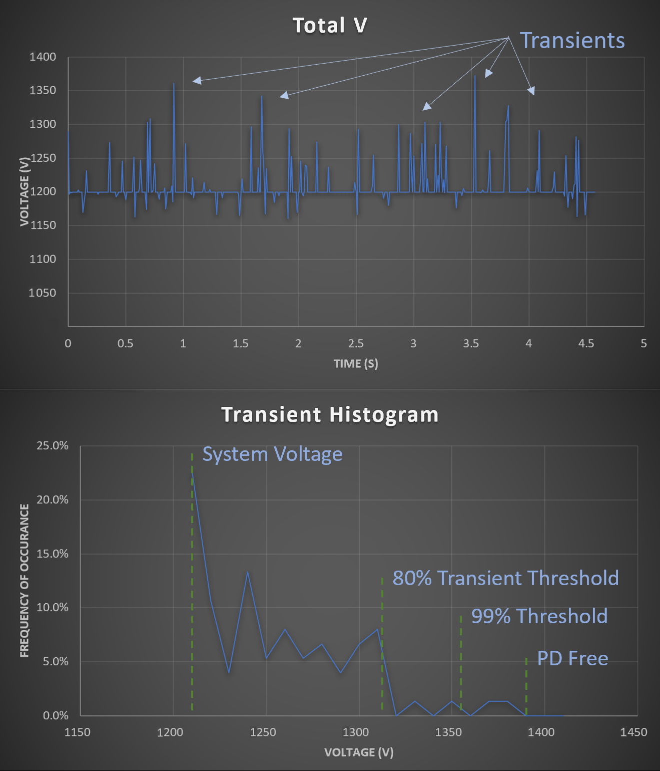
System transient voltage data should be used to help drive design decisions for the aircraft wiring system components. Here is a representative waveform for a circuit showing significant noise resulting in voltage peaks nearly 200V above the system voltage. Looking at the frequency of occurrence, perhaps components with PD at 1300V might be acceptable if it can be shown they can withstand service conditions for a defined service life (either life limited or for the full aircraft service life).
Of course, this then leads to the question of what percentage of these transients must be dealt with to protect the EWIS design. Consider this, if 99.9% of voltage transients occur below 2000V and the last 0.1% occurs in the range between 2000V and 3000V, should the wire design be PD-free to at least 3000V? Here, there is no right answer.
If the wire is designed for 3000V, then it is very likely to have thicker and/or heavier insulation which are two design elements often avoided in aerospace applications. But it is a safe approach and certainly, there is nothing wrong with being conservative. This approach does not require any additional data to justify the decision and it is easily implemented in the system. An alternative is to select a thinner and lighter wire that has a voltage rating of less than 3000V and accept that during the standard service conditions, PD will occur. From here, testing is then necessary to determine the long-term reliability of the wire or other EWIS components under these PD conditions.
High Voltage Longevity
How is long-term voltage longevity determined? This can be done with accelerated aging testing. For this test, the component is placed in a controlled environment and subjected to repeat high voltage spikes for a specified duration with the system set up such that the component under stress is in direct contact with the ground or voltage return. The application, shape, capacitance, voltage, frequency, and duration of this type of test are established before test performance. During the accelerated aging test, the component is monitored to identify if there is a voltage breakdown and when it occurs. Ideally, the component survives the accelerated aging without any dielectric breakdown failure. After the exposure, additional testing is performed to assess the component’s performance, such as insulation resistance, the PDIV, PDEV, and visual inspection.
For those looking for a panacea, no wire or cable producer is going to be able to provide this data on any standard high voltage product. Because of the unique nature of every power system being fielded, it is impossible to generate a generic data set applicable across most of the end-users. That is until there is a better understanding of high voltage degradation, polymer degradation, and fleet experience to help drive background research and development of degradation models. Until that occurs, OEMs will need to perform this testing of their components, and either a) PDIV/PDEV exceeds the maximum system voltage plus transients plus derating factors or b) Perform extended voltage endurance testing.
More to Come
High voltage electrical systems are a fact of the new generation of air vehicles. Because of this, new means of assessing the wiring system components must be employed to ensure the safety and long-term reliability of these components. It is very likely that multiple approaches will be implemented across the industry, but whatever those approaches are, they must have the supporting documentation to ensure that the components will be reliable throughout the life of the vehicle or that there is a scheduled replacement of these high voltage components. And certainly, given the potential cost of any rewiring effort, selecting the correct components and the best components for the application is critical. Lectromec can help you and your organization develop the test plans and testing needed to verify your fielded components. Contact us to find out more.

Michael Traskos
President, Lectromec
michael.traskos@lectromec.comMichael has been involved in wire degradation and failure assessments for more than a decade. He has worked on dozens of projects assessing the reliability and qualification of EWIS components. Michael is an FAA DER with a delegated authority covering EWIS certification and the chairman of the SAE AE-8A EWIS installation committee.