Key Takeaways
- Under high voltage conditions, insulative materials are likely to experience partial discharge.
- Determining partial discharge inception and extinction voltages for a given material is crucial for setting a safe operating voltage range.
- Testing in a controlled environment is key to assessing the impacts of variable factors (temperature, frequency, altitude, etc.) on partial discharge inception and extinction voltages.
The use of voltages greater than 300V means that a new failure mechanism must be considered – partial discharge (PD). Historically, partial discharge testing at the component and system level was typically “not applicable”, but it has emerged as an important factor in aerospace applications (something Lectromec has covered in several articles). Because PD testing typically yields a pair of values (partial discharge inception and extinction voltage), there are many implications of those two numbers. PD can impact component selection and may be used to assess wiring system condition/health. In this article, we discuss what PD test results mean at the component and system levels.
Basics of Wire/Cable Partial Discharge Testing
Partial discharge is an electrical discharge that occurs within an insulation system when the voltage stress exceeds the dielectric strength of the insulation (think of a coax cable with voltage on the center conductor and neutral on the shield). These short, low-energy, discharges will progressively degrade an insulator and lead to insulation breakdown. The time to failure is impacted by several factors that include:
- Applied voltage
- Insulation type/construction
- Insulation thickness
- Power system type (AC/DC)
- System temperature
- System altitude
In wiring system components, PD testing is conducted to detect at what voltage the partial discharge will start, then slowly lower the voltage until the partial discharge stops; these are identified as the Partial Discharge Inception Voltage (PDIV) and Partial Discharge Extinction Voltage (PDEV), respectively. Because the PDIV will result in local ionization, the PDEV may be hundreds of volts lower than the PDIV, which depends on the factors identified above.
Impact of Factors on PDIV
When performing tests to determine component’s PDIV/PDEV performance, the test must be performed under controlled conditions to ensure accurate and repeatable testing is performed. The following discusses the impact of each of the parameters.
Temperature: While most PD testing is performed at ambient temperatures, test performance at different temperatures can be performed. The impact of temperature on PD test values does not change significantly within lab conditions (e.g., the change in PDIV test results at 18oC versus 23oC would be below the test’s margin of error). In general, higher temperatures will decrease the PDIV, as elevated temperatures can weaken the insulation material and increase the likelihood of partial discharge activity. Some testing performed by Lectromec has found that long term thermal exposure of some insulations will show an increased PD level; Lectromec theorizes that the long-term thermal exposure increased the adhesion in the multilayered insulation system causes a reduction of voids leading to a PDIV increase.
Frequency: The power supply voltage may also impact PDIV results. Testing is typically performed with 60Hz power and, similar to temperature, slight power supply variations will not impact the PDIV results. The PD testing may be performed at different frequencies, and testing at higher frequencies will result in a PDIV reduction. Those seeking to determine the PD performance for PWM systems should focus on test frequencies that align with the PWM risetime. For example, a PWM system with a rise time of 20ns should consider PD testing with a 12.5MHz waveform.
Note: PD testing with DC power is a challenge as it is difficult to detect the DC PD. Whereas AC voltage ‘resets’ the system each cycle and creates repeat opportunities to observe the high-frequency PD energy release. The DC PD activity often starts strong when the voltage is first applied but diminishes over time as charge redistribution occurs. It is for this reason that AC PD is recommended for most applications.
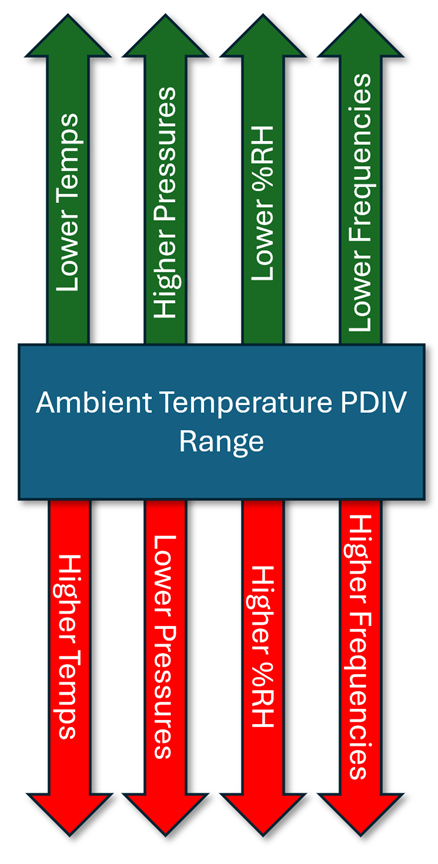
The PVID of an insulative material is impacted by many environmental factors that must be considered for use on aircraft.
Environmental Conditions: Factors such as humidity, contamination, and mechanical stress can impact PDIV by altering the insulation material’s dielectric properties. If a sample is exposed to a high humidity environment for an extended period, and the material is one that will absorb moisture, then the PDIV levels will likely decrease. Unless otherwise specified, it is recommended that the test sample is left undisturbed in the lab environment for at least 24 hours before testing is performed.
Physical Conditions: The physical setup of the sample under test can impact test performance. When testing coax cable, the physical configuration, such as being wrapped around a mandrel, does not have a significant impact unless there is a tight bend or mechanical strain on the cable compressing the dielectric. Where physical conditions can have a great impact is in shielded, multi-conductor cables where compression can change the component conductor positioning and the shared surface area of the component wires. This is a difficult parameter to control as the positioning of each component wire within the cable is impossible. As such, PD testing of multi-conductor cables should include several trials to capture the sample’s variability.
Outputs of PD Testing and Interpretation
The primary outputs of PD testing include the PD inception and extinction voltages. Depending on the test standard, multiple trials may be performed to assess the sample’s PD variability. Typically, the average PD VRMS is reported with the PD results.
The interpretation of the PD results depends on the use case. In most cases, a safe level to run a system continuously is typically below the PDEV value. While it would be possible to operate a system above PDEV but below PDIV, it is recommended to avoid this scenario. The rationale for this is that, if a voltage spike creates a peak voltage above PDIV, then the PD would continue indefinitely or at least until the system is turned off. Furthermore, maintaining a sufficient margin between PDIV and operating voltage, including the consideration of the derating factors discussed above, ensures a safety buffer against insulation breakdown.
Setting a safe operating level presupposes a limited degradation of the insulating material during its operational life. However, if the material does degrade over time, this must also be considered in the safe operating level determination. Depending on the operational characteristics, the material properties, and the types of voltage applied to the system, the derating factor from partial discharge inception voltage may be 1.3, 1.5, or even 2.0 less than PDIV. Only by understanding the system can it be possible to pick a safe operating level.
Magnitude and Nature of Partial Discharge
The magnitude and characteristics of partial discharge activity observed during testing provide insights into the severity and location of potential insulation defects. Typically, the sensitivity required in aerospace cable specifications for PD detection is 5pC. Would there be value in changing this threshold?
- A lower PD detection threshold is possible, but it does mean there will be a lower signal-to-noise ratio. From a practical approach, the lower PD detection will likely be a limited change in system voltage but might have a large impact on part selection and fabrication for a small benefit. Remember, the lower PD detection threshold corresponds with a lower PD energy. This lower energy will also likely have a much lower impact on the insulation, if there is any degradation at all at these low energies.
- A higher PD detection threshold (say 10pC) typically would yield a higher PDIV/PDEV. The concern then becomes, if the goal is for the fielded system to have a voltage to be below the 10pC threshold, whether the acceptable system voltage is still at a level high enough to generate PD.
Conclusion
Partial discharge testing serves as a valuable tool for assessing the health and reliability of wire and cable systems. Understanding the implications of PD test results, including PDIV, PDEV, and factors influencing their values, is essential for ensuring the safety and longevity of critical EWIS components. The proper interpretation means the decisions regarding maintenance, repair, and operation strategies, thereby minimizing the risk of costly downtime and ensuring continued operational integrity. To find out more about how to assess the PD performance of your components, contact Lectromec.

Michael Traskos
President, Lectromec
michael.traskos@lectromec.comMichael has been involved in wire degradation and failure assessments for more than two decades. He has worked on dozens of projects assessing the reliability and qualification of EWIS components. Michael is an FAA DER with a delegated authority covering EWIS certification and the former chairman of the SAE AE-8A EWIS installation committee.