Key Takeaways
- VSWR is a common means to determine system performance, but may not be effective to find limited cable damage.
- TDR can be helpful in finding broken or shorted wires, but ineffective for limited cable damage.
- A wire or cable’s acceptable damage threshold is not binary. However, data is needed before any changes to maintenance procedures are made.
In the last article, Lectromec introduced a damaged coaxial cable and tried three techniques to distinguish it from an undamaged cable. The standard multimeter tests (capacitance, inductance, and resistance measurements) found no appreciable difference.
The idea of this evaluation was to demonstrate that the classic multimeter, while a great tool, is not suitable for detecting damage to coaxial cables.
But we cannot run an article and leave it without a solution. In this article, we continue the testing of a damaged coax cable to see what technology, if any, can identify and perhaps locate the damaged section of cable.
History
Because of the impact wire failures can have on system performance, wire fault detection has been a field that has benefited from a wide range of research. In addition to the research executed by companies, a decade of research efforts was funded by NASA, the FAA, and the US DoD following TWA800 and SwissAir111. To support research tin wiring fault detection, Sandia National Labs (SNL) built a testbed of aircraft wire harnesses with various types of physical damage.
With 5mm of shield and jacket damaged at the center of a coaxial cable, it should be pretty easy to detect the damage? Testing suggests otherwise.
While some fault types in the SNL testbed were easy to identify (hard short and broken conductors) there was a lot of damage that could not be detected by automated technologies. This created the red-green problem: An engineer could fine-tune the system to identify a potential fault, but to automate the system to provide simple Red-bad Green-good for an untrained installer/technician was a significant challenge and often left only the most basic fault detection. To quote NASA’s “Aging Aircraft Wiring Fault Detection Survey” published in 2007,
“The broad [wiring] failure categories cannot be easily mapped to the physics of degradation of wiring insulation and the corresponding electromagnetic characteristics”.
Attenuation Testing
The idea of attenuation testing is to send a signal down the cable at one frequency or across a wide frequency spectrum and measure the signal strength at the other end of the cable (the weaker the received signal, the greater the attenuation). Typically, higher frequency signals are more susceptible to attenuation as a result of cable damage.
The accompanying figure shows the results of the damaged [blue] and virgin [red] cables. The spectrum tested ranged from 100kHz to 3.4 GHz (the M17/111 cable is rated for use at frequencies up to 3GHz). With attenuation testing, the greater the signal loss (-dB) the worse the cable is performing. The attenuation tests show no appreciable difference between damaged and virgin cables. While the damage does appear to be significant (destroyed shield, some damage to the dielectric), the test data shows, from an electrical performance perspective, this level of damage has a minor impact, at least in a benchtop evaluation.
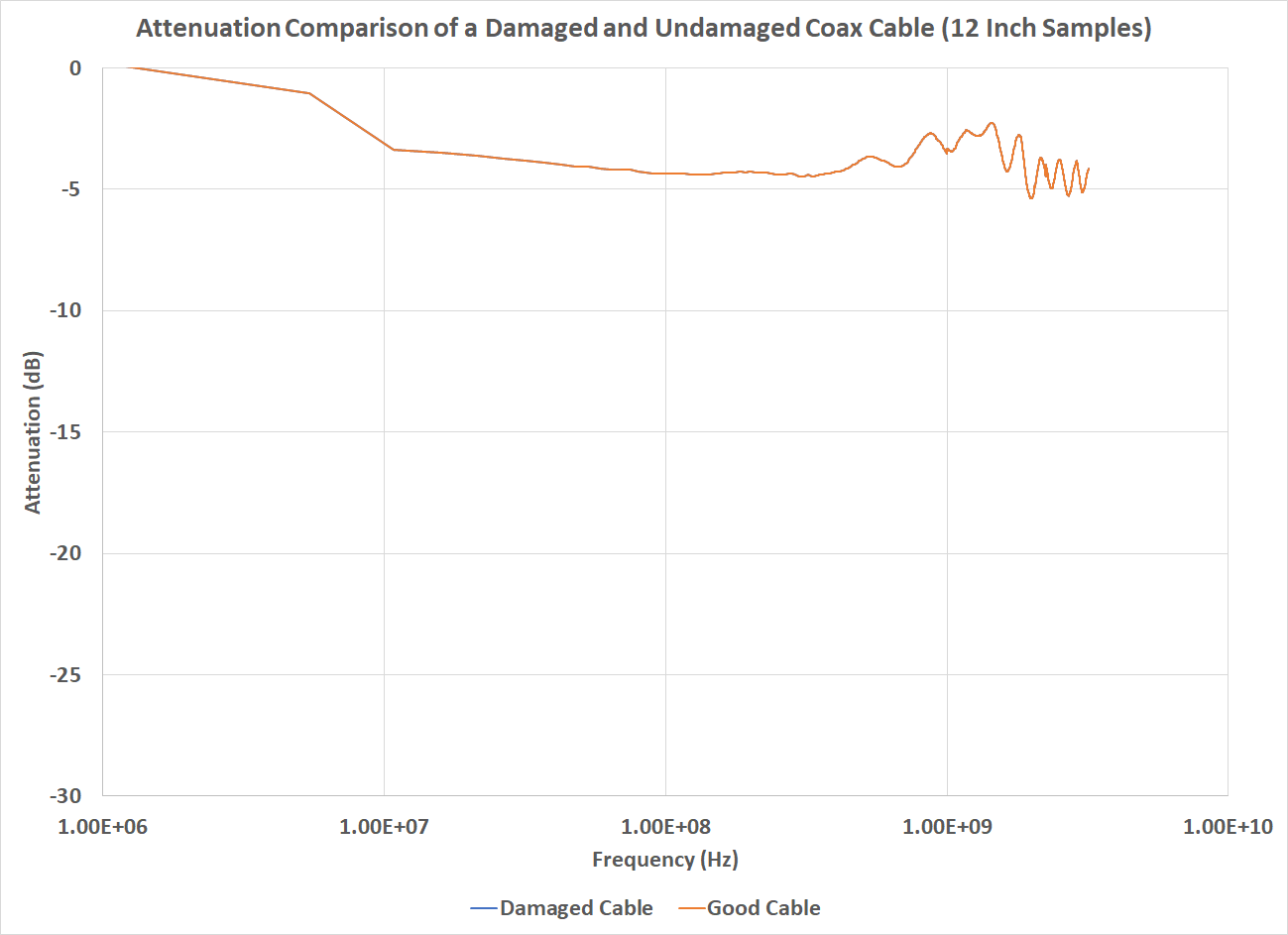
Attenuation graph of both damaged and undamaged coax cables.
Voltage Standing Wave Ratio
Voltage Standing Wave Ratio (VSWR) is the concept that energy that is transmitted should be absorbed/transmitted by the signal’s target (a signal should be received and not bounce back to the sender). From a physics perspective, the VSWR is a means to measure the consistency of a system’s electrical impedance; impedance mismatches (such as attaching a 50 Ohm cable to a 75 Ohm connector) creates signal reflections. For those with a strong EMI background, the VSWR is proportional to the s11 parameter.
Because the VSWR is dependent on the system impedance, the capacitance and inductance measurements reported in the previous article would suggest no appreciable difference between the damaged and undamaged cables would be detected. However, the LCR meter used for the evaluation described in Part 1 operates at 10kHz and the VSWR meter used here operates across a broad frequency range.
| Frequency (MHz) | Virgin Sample | Damaged Sample |
| 300 | 1.19 | 1.20 |
| 500 | 1.25 | 1.27 |
| 700 | 1.37 | 1.26 |
| 1000 | 1.66 | 1.74 |
The VSWR results are shown in the accompanying table. The results show very little change between the two samples. The small variances between the two samples are within the expected cable construction variability (i.e. the variation in connector crimps, cable bend, etc.).
Those interested in this can see more about this test method outlined in MIL-PRF-39012 Method 4.6.11
Time Domain Reflectometry
Time Domain Reflectometry (TDR) relies on a similar concept as the VSWR. Whenever there is a change in impedance, some part of the signal is reflected to the source. When the impedance match is small (such as damage to a coax cable shield), the reflected signal is also small; when the impedance match is large (such as at the end of the conductor), the reflected signal is also larger.
TDRs have been a part of wire/cable diagnostics for decades and can help to identify the location of a wire/cable fault to within 24 inches (frequency and equipment dependent). This is possible because the speed of signal transmission (velocity of propagation) is an established parameter for most cables. Knowing the time at which the signal left the transmitter, its speed, and when it returns, it is possible to calculate the distance traversed.
The reflected signal is shown in the accompanying figure. If the damage was detectable, the reflected signal would have additional ripples. Unfortunately, the damage is not large enough to impact the signal.
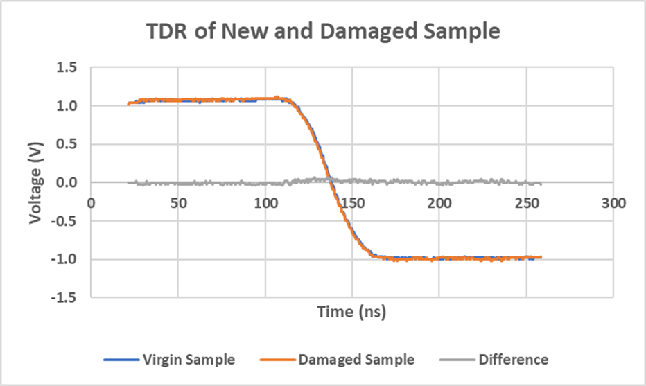
If there was sufficient damage to the cable that it would impact the capacitance and impedance, the TDR would identify a change in characteristic impedance. This was not the case with the test sample.
Conclusion
When Lectromec started on these articles, the intent was to show that multimeters would not be able to detect coax cable damage – which we did. However, we anticipated the damage would be detectable through more advanced tooling and fault detection techniques, but this also proved to fall short.
This can be considered positive from a system reliability standpoint; some types of coax cable may be robust enough to endure damage without impacting system performance. The testing performed by Lectromec was executed in a lab setting and was limited to 3GHz signals, but the results still point to a robust cable design.
From a system maintenance perspective, this also means that the accumulated damage across a coax cable might be undetectable until several cable damage events have accumulated. It might also suggest that maintenance actions could potentially be amended to allow for some coax cable damage. Before any changes are made, it is necessary to fully understand the connected systems, represent the electrical environment (potential EMI), and gather additional data to support such a change.
For those looking to get a better grasp on damage tolerances of EWIS components, contact Lectromec. Our ISO 17025 accredited lab specialized in aircraft wiring system testing, analysis, and certification.

Michael Traskos
President, Lectromec
michael.traskos@lectromec.comMichael has been involved in wire degradation and failure assessments for more than a decade. He has worked on dozens of projects assessing the reliability and qualification of EWIS components. Michael is an FAA DER with a delegated authority covering EWIS certification and the chairman of the SAE AE-8A EWIS installation committee.