
Understanding Filter line Cables: Purpose, Construction, and Key Concepts
Introduction to Filter line Cables
Filter line cables play a crucial role in modern electronic systems, where electromagnetic interference (EMI) and radio frequency interference (RFI) can significantly affect performance and reliability. Designed to reduce these interferences, filter line cables ensure that only the desired frequencies pass through and maintain signal integrity. While filter line cables are not the only solution for maintaining signal integrity down a circuit, they are another tool available to Electrical Wiring Interconnection System (EWIS) engineers.
Purpose
The primary purpose of filter line cables is to minimize EMI and RFI, which are prevalent in environments with high levels of electromagnetic noise. These interferences can disrupt electronic devices, degrade performance, and lead to equipment malfunction. Filter line cables, such as AS85485 style cables do this by filtering out unwanted noise. Performance characteristics of filter line cables include:
- Noise Reduction: Minimize EMI to prevent electronic system disruptions.
- Signal Integrity: Maintain data transmission fidelity.
- Enhanced Performance: Improve reliability in noisy environments.
Construction of Filter Line Cables
Filter line cables are designed with multiple layers and components to effectively filter frequencies outside of a designed bandwidth. Key elements of their construction include:
- Conductors: Made of copper or aluminum, these serve as the primary pathways for electrical signals. They can be single or multiple strands, depending on the application (for aerospace applications, multiple strand conductors are recommended – AS50881).
- Insulation: Each conductor is coated with an insulating material.
- Shielding: Effective shielding is critical for reducing EMI. Filter line cables typically use a combination of:
- Foil Shield: A layer of metallic foil wrapped around the conductors.
- Braided Shield: A woven mesh of thin metallic strands, providing additional protection against high-frequency interference.
- Combination Shield: Utilizing both foil and braided shields for maximum EMI/RFI protection.
- Filter Elements: Integrated components like ferrite beads or chokes suppress high-frequency noise. These can be embedded within the cable jacket or attached externally.
- Drain Wire: Running along the length of the cable in contact with the shield, the drain wire aids in grounding, enhancing EMI/RFI protection.
- Outer Jacket: The entire assembly is encased in a durable, insulating material, protecting the cable from environmental factors such as moisture, abrasion, and chemicals.
- Optional Layers:
- Armor: Additional metallic braid or tape for extra mechanical protection in harsh environments.
- Separator Layers: Tape may be used to separate different shielding layers, adding mechanical strength and stability.
- Purpose:
- Filter line Cables: Primarily designed to reduce EMI/RFI.
- Coaxial Cables: Used for transmitting high-frequency electrical signals with minimal loss.
- Construction:
- Filter line Cables: Multiple conductors, complex shielding, and integrated filter elements.
- Coaxial Cables: Single central conductor, dielectric insulator, and metallic shield.
- Performance:
- Filter line Cables: Excellent noise suppression and signal integrity in noisy environments.
- Coaxial Cables: Efficient high-frequency signal transmission with minimal loss.
- Low-Pass Filters: Allow frequencies below a certain cutoff to pass while attenuating higher frequencies.
- High-Pass Filters: Allow frequencies above a certain cutoff to pass while attenuating lower frequencies.
- Band-Pass Filters: Allow a specific range of frequencies to pass while attenuating those outside this range.
- Filter Sharpness: The width of the transition band indicates the filter's sharpness. A narrow transition band means a sharp cutoff, while a wider transition band indicates a gradual cutoff.
- Performance Indicator: The transition band shows how effectively the filter can prevent unwanted frequencies from passing through.
- Design Trade-offs: Achieving a narrow transition band often requires more complex and costly filtering components. A wider transition band is often cheaper and easier to achieve but less effective.
- Definition: The frequency range where the signal is heavily attenuated, reducing its amplitude significantly to prevent interference.
- Importance: Ensures noise suppression and signal integrity, helping meet electromagnetic compatibility (EMC) requirements.
- Example of Attenuation Level: Effective stop bands might have attenuation levels of 30 dB or more, reducing the signal strength to less than one-thousandth its original level.
Comparison to Coaxial Cables
While Filter line cables and coaxial (coax) cables may appear similar, they serve different purposes and have distinct construction and applications.
Description of the PTS bands
Understanding the frequency response characteristics of Filter line cables is essential for designing effective filtering solutions. Three key concepts in this context are the pass band, transition band, and stop band.
Pass Band
The pass band of Filter line cables is the frequency range that the cable allows to pass through with minimal attenuation. This range is tailored to the specific requirements of the application. For instance, in communication networks, the pass band might cover the range of frequencies used for data transmission, while in medical devices, it might be tailored to the frequencies of interest for monitoring or diagnostic equipment.
Filter line cables can be designed as low-pass, high-pass, band-pass, or band-stop filters, depending on the application:
Transition Band
The transition band is the frequency range over which the cable transitions from pass band to the stop band. The transition band represents a sharp decline in transmission performance the filter can differentiate between desired and unwanted frequencies.
Stop Band
The stop band is the range of frequencies that a filter line cable is designed to significantly attenuate or block. This band is crucial for eliminating unwanted noise and interference, ensuring that only the desired signals are transmitted with minimal interference.
As an example, the following table shows pass, transition, and stop band performance requirements for M85485 cables (superseded by AS85485). Note that the attenuation values are in dB/ft and that the stop band attenuation must be greater than 30 dB/ft. For this reason, stop band measurements are often done on lengths of cable less than a foot such that the measurement can be captured by common lab equipment.
| Part no. | Pass band (dB/ft) | Transition band (dB/ft) | Stop band (dB/ft) | ||||
|---|---|---|---|---|---|---|---|
| 1.0 MHz | 10.0 MHz | 100 MHz | 500 MHz | 1000 MHz | 1 to 18 GHz | ||
| (max) | (min) | (max) | (min) | (min) | (min) | (min) | |
| M85485/5-22-* | .015 | .04 | 0.10 | 1.3 | 12 | 30 | 30 |
| M85485/5-20-* | .015 | .04 | 0.10 | 1.3 | 12 | 30 | 30 |
| M85485/5-18-* | .015 | .04 | 0.10 | 1.3 | 13 | 33 | 33 |
| M85485/5-16-* | .015 | .04 | 0.10 | 1.3 | 13 | 33 | 33 |
| M85485/5-14-* | .015 | .04 | 0.10 | 1.3 | 13 | 33 | 33 |
| M85485/5-12-* | .015 | .02 | 0.10 | 1.3 | 12 | 30 | 30 |
| M85485/5-10-* | .015 | .02 | 0.10 | 1.3 | 12 | 30 | 30 |
Use and Installation
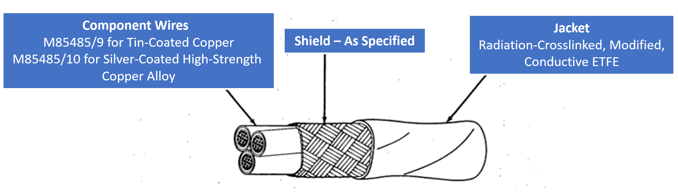
Depending on the cable construction, some filter line cables will have a conductive jacket such as AS85485/12 which has a conductive ETFE jacket. This jacket conductivity for these cables is controlled with a maximum resistance of less than 150 Ohms/cm (significantly lower than a traditional ETFE jacket that might be used for a NEMA27500 cable). This jacket resistance means that, rather than conducting the electromagnetic energy, the jacket will convert it to heat.
Because of the unique nature of the conductive jacket, special precautions are needed for the cable striping, termination, and installation of the cable. Guidance on handling, bundling, termination, and repair techniques can be found in the SAE AIR4465.
When considering the EWIS separation requirements of FAA regulation 25.1707, EWIS must be installed to ensure safe operation and that EWIS faults will not create hazardous conditions. The details of what must be considered are identified in AC 25.1701-1, stating:
“§ 25.1707 does not mandate specific separation distances. Instead it requires that the chosen separation be adequate so that an EWIS component failure will not create hazardous effects on the airplane or its systems. The following factors should be considered when determining the separation distance… h) Possible EMI, HIRF, or induced lightning effects.”
For certain applications, filter line cables may be the most appropriate technology to mitigate achieve the performance requirements.
Conclusion
Filter line cables are indispensable in environments where EMI and RFI can affect electronic systems' performance and reliability. Their complex construction and careful design ensure effective noise suppression and signal integrity, making them suitable for various applications. Understanding the concepts of pass band, transition band, and stop band is crucial for designing and utilizing Filter line cables effectively. For those looking to assess the performance of your filter line cables, contact Lectromec; we have the knowledge and equipment to test and qualify your cables. Contact us today to find out more.