
IEEE 1584-Arc Standard
Research down an unfamiliar path often includes seeking guidance from others or other fields who have gone through the process before. For those seeking information and guidance on electrical arc damage, one reference that some have considered for aerospace applications (other than the articles available on Lectromec’s website) is the IEEE 1584 standard. Here we have a brief overview, discuss concepts the document covers, and a comparison of some of the results versus arc damage data gathered for aerospace applications.
The Purpose
The IEEE document covers the potential dangers of arc flash. To quote directly from the standard
"The purpose of the guide is to enable qualified person(s) to analyze power systems for the purpose of calculating the incident energy to which employees could be exposed during operations and maintenance work. Contractors and facility owners can use this information to help provide appropriate protection for employees in accordance with the requirements of applicable electrical workplace safety standards."
Can some of the lessons here be applied to what is needed for aerospace such as 25.1707? That is our objective in this article.
Separation Distance
The core of the IEEE 1584 document is the set of formulas for calculating the necessary safe separation distance for personnel. These long and complicated formulas cover the wide range of possibilities from low current lower voltages to higher current and higher voltages. When these are examined and applied, a set of results that are generated.
Range of the Model
Models (at least the good ones) have an acceptable range. This limits their application to scenarios that match the testing evidence. Here are the boundaries for this model:
- Voltage: 208VAC - 15kVAC (three-phase)
- Frequency: 50 or 60Hz
- Fault Current for 208V - 600V: 500A - 106kA
- Fault Current for 601V - 15kV: 200A - 65kA
- Gap between Conductors 208V - 600V: 0.25in - 3in
- Gap Between Conductors 601V - 15kV: 0.75in - 10in
There are also limits on the working distance and maximum enclosure size, but these are not important for the application here other than the enclosure size is compatible with aircraft enclosures.
There are a couple of items that stand out from the boundaries (at least for us in the aerospace industry)
- The working frequency maximum is 60Hz. For most aircraft applications, AC power works on the range from 300 - 800Hz. From Lectromec's arc testing experience, the impact on total arcing energy between 60 and 400Hz is limited. While there are finer details at work with these frequencies, the results should be close.
- The model only works for AC systems. Those looking for DC arcing models have to look elsewhere. Lectromec has discussed DC arcing in other articles.
- The minimum fault current for the low voltage system is 500A. Arc faults of 16AWG and smaller are likely to have fault currents below this value. For 20AWG wire, the wire length from the distribution to fault location would have to be less than 20ft (208 volts phase to phase, 0.9 ohms per 100ft of 20AWG wire). Lectromec and FAA research has shown the most severe distance from the power source for such conditions is between 100-150 ft. This is due to a combination of the fault current and circuit breaker response time.
So, while these limitations do place the model outside the parameters for most aerospace applications, we examine the model results and how they stack up against historical aerospace-centric arc test data.
The Formula
First, an item of note when reviewing the IEEE 1584 is that there are several equations whose use is dependent on the voltage level ( ≤ 600V, 600V, 2700V, and 14300V). This makes sense in the ionization caused by the event is likely to be different as is the separation distance.

The formula has several inputs that include several coefficients (the ‘k’ parameters that are based on the selected equation), the bolted fault current, configuration of conductors, and the event duration. The configuration of the conductors may be:
- Horizontal conductors in open air
- Horizontal conductors in conductive box
- Vertical conductors inside a metal box
- Vertical conductors in open air
- Vertical conductors terminated at an insulating barrier inside of a metal box
For the examples here, the horizontal conductors in open-air values are used.
Circuit breaker response time is also part of the calculation. Those using thermal circuit breakers will have to make a best guess on the circuit breaker trip time based on the combination of system voltage and circuit plus arc resistance. Using a min/max time duration approach is suggested here.
From all of this, the formula yields an output in joules per centimeter squared. Alone, this value has little meaning. However, those with additional modeling capacity can use this as an input.
But from an application perspective, the goal is to determine safe distance. In the document, this value is specified as the arc flash boundary and is where, “the distance from a prospective arc flash where the incident energy is 5.0J/cm2”. In effect, this is the minimum “safe” distance.
Similar to the energy calculation, the Arc Flash Boundary (AFB) equation is long and requires several inputs.

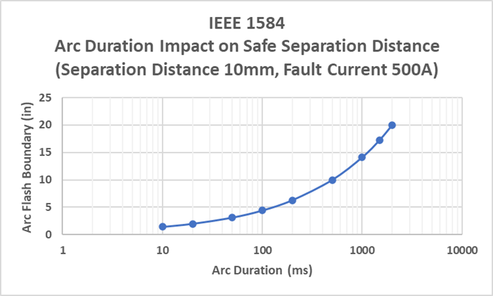
The following graph shows a representation of the arc flash boundary for the following configuration:
- 10mm separation distance between conductors
- 500A fault current
- Horizontal in open air
Reviewing the graph, we see that an event as short as 100ms (which is practical for a 35A thermal circuit breaker), the arc flash boundary is 4.4 inches. In comparison, a 10ms arcing event (practical for 7.5A and 15A circuit breakers), sets the arc flash boundary at 1.5 inches. As expected, the increased arc duration results in a larger arc flash boundary.
What is the issue?
The key to remember with the results and the graph shown here is the arc flash boundary considers the safe distance for human flesh. The use of human flesh for this model means a conservative estimate given that skin is more susceptible to electrical damage then aircraft components such as wiring fuel tanks and hydraulic lines.
Comparing the IEEE 1584 calculations to test data generated by Lectromec and the FAA, we find that the IEEE standard is conservative by a factor of 2 (in preparation of this article, not every configuration was examined and compared, but the data points examined confirm this factor of 2 value). While the aerospace industry does prefer conservative estimations and erring on the side of caution, creating larger separation distances creates a whole new set of challenges. In particular, attempting to route wire around other aircraft components with double separation distance is a challenge in tight areas such as the wings.
Conclusion
The IEEE standard does provide a good basis for the protection of personnel from electrical arcing damage and has value in its application related to power distribution systems. However, the calculations cannot be taken at face value when they are applied to other systems or the target is something other than human skin.
For a better understanding of the requirements and a means to address them, there is the Lectromec white paper discussing many of the factors that must be considered for electrical arcing and damage to aircraft components.