
Effects of high voltage on aircraft wire connectors
One of the challenges that exist in modern aircraft design is performing more with less. That means using less space, less power, and less weight. For the most part, the technologies integrated into aircraft systems have been able to achieve these goals. Along with this push is a drive to place higher voltages on electrical systems. In previous articles, we have discussed the impact that these high voltages may have on the wiring. Today, we look into what may be the weakest part in the chain of designs that involve these higher voltage systems: the connectors. Specifically, we will examine the effects of high voltage on aerospace wire connectors.
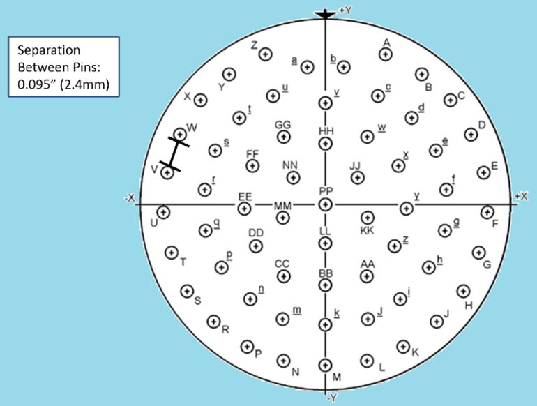
The modern connector constructions have improved significantly over the 12 iterations of the MIL-C-38999 standard as the most common connector design. These connectors have a wide range of pin setting and can have connectors that have as few as two pins and as many as 61 pins. Obviously the high-density connectors are more compact with less spacing between pins. When put into practice, the pin spacing of the MIL-C-38999, which uses MIL-STD-1560 as a series, can be as little as 2.4mm. What does this mean in an application?
Harness Testing
When performing a performance or quality check on a completed harness, it is common to do a pin-to-pin ohm check or use a high voltage device, like a Megger®, to find shorts between wires. As part of the more advanced harness checks, automated wire testing systems (AWTS) like Eclypse or DIT-MCO can be used. The AWTS systems work by connecting to the entire harness and performing a variety of checks that include continuity, finding conductor breaks with Time Domain Reflectometry (TDR), and finding shorts to ground or other wires. When these tests are performed with AWTS equipment (which can be automated), a high voltage may be applied to the wires in hopes of finding breaches.
What is the Maximum Safe Voltage to Test a Harness?
Aircraft wiring experts have a general rule of thumb. At sea level, it takes 1000V to cross a 1mm gap, and that scales fairly linearly as the voltage increases. If we look at our connector example, that would suggest that we would need to use less than a 2500V differential (peak voltage, not RMS) between two pins and still be safe (safe is defined here as not having energy jump from one pin to another). For a system using this particular connector, it would be good practice for any harness testing system to limit the test voltage below this limit.
Applying to Systems
Therein lies the problem for many systems. There is no single general solution that will apply to all areas of the aircraft. There are several factors that should be considered before using a dielectric tester on any application:
- Many connectors have smaller pin spacings.
- Many harness testers are used off-the-shelf without an understanding of the applied system.
- Caution should be taken when testing on or near fuel quantity indicator system wiring (to be covered in a future article on SFAR88).
In Lab Testing
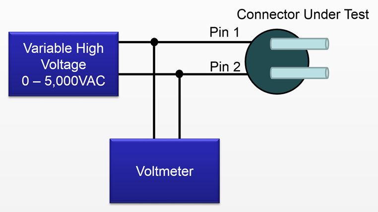
In the video shown here from Lectromec's lab, demonstration was run of using an uncontrolled high voltage on an MS24264 connector. The first photo provides a layout of the system. A variable high voltage power supply was connected to two pins of the connector while the voltage was slowly increased until a consistent arc occurred.
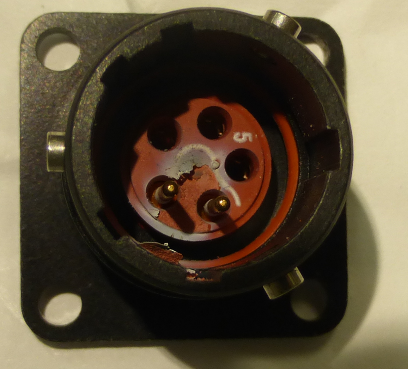
This last photo shows a close up of the connector after just 30 seconds of high voltage exposure. There is visible wear on the pins with some damage to the insert. Although there was no physical damage to the pins (the test current was limited), there was charring of the pins. For the five pin connector that was used in the test, it is easy to see the damage to the insert and contamination, but for higher density connectors, this becomes more difficult. Further, the contamination, if not cleaned, can impact circuit performance.
Summing it Up
The obvious goal of the harness testers is to find any insulation breaches so that they may be repaired or replaced. However, use of low voltages, such as 500V, will also limit the distance from ground and/or return circuit that the device will find. To increase the sensitivity and number of faults found, the voltages need to be increased. There is a balancing act between finding faults, causing damage to the components, and the practical application limits of the systems being tested. What it comes down to is that there needs to be a limit to this voltage, because the system designs pushing for higher density connectors are making it harder and harder to find faults without damaging the components.