
Comparison of MIL-DTL-38999 and MIL-DTL-22992
In aviation Electrical Wiring Interconnection Systems (EWIS), the MIL-DTL-38999 is nearly synonymous with connector testing. The standard is comprehensive, robust, and serves as a good test reference for nearly any electrical connector, even those that do not align with the entire standard. Connectors qualified to the 38999 are considered suitable for rather extreme aviation environments, namely: high vibration areas, SWAMP environments, and even within weapons systems. Because of its robustness, the test/performance requirements of the MIL-DTL-38999 can sometimes be too restrictive for less intense aircraft environments (such as commercial or low-altitude aircraft) or for EWIS connectors that do not align with the construction of MIL-DTL-38999’s “miniature, high density, circular, environment resistant electrical” connectors.
In these cases, other standards may be considered to more closely align with the anticipated needs of an aircraft’s EWIS. In this article, we will compare the well-known MIL-DTL-38999 with a much less restrictive standard, MIL-DTL-22992, and identify many similarities and gaps between the two standards.
Basic Differences
Some of the most obvious differences between standards include the scope and intended use cases of each standard.
MIL-DTL-38999 |
MIL-DTL-22992 | |
| Temperature Range | -65°C to 200°C | -55°C to 125°C |
| Minimum Contact Size | 23 | 16 |
| Maximum Contact Size | 8 | 0000 |
| Construction |
|
|
| Plug Types |
|
|
| Receptacle Types |
|
|
| Use Cases |
|
|
Notably, the MIL-DTL-22992 lacks considerations for altitude, flame testing, and thermal aging methods. This is not too surprising given the significantly less severe environments the standard addresses, but it is important to keep in mind these gaps when using MIL-DTL-22992 for connector qualification testing.
Test Alignment
There are a limited number of test methods between MIL-DTL-38999 and MIL-DTL-22992 that align with one another to varying degrees of accuracy. The following table provides a simplified comparison of tests common between both standards.
Test |
Referenced Methods |
38999 |
22992 |
|
38999 |
22992 |
|||
Air Leakage |
EIA-364-02 |
None |
|
|
Insulation Resistance |
EIA-364-21 |
EIA-364-21 |
|
|
Insert Retention |
EIA-364-35 |
None |
|
|
Dielectric Withstanding Voltage |
EIA-364-20 |
EIA-364-20 |
|
|
Salt Spray |
EIA-364-26 |
EIA-364-26 |
|
|
Contact Resistance |
EIA-364-06 |
EIA-364-06 |
|
|
Hexavalent Chromium Detection |
IEC 62321-7-1 |
IEC 62321-7-1 |
|
|
Magnetic Permeability |
EIA-364-54 |
ASTM A342 |
|
|
Shell-to-Shell Conductivity |
EIA-364-83 |
EIA-364-83 |
|
|
Contact Retention |
EIA-364-29 |
None |
|
|
High Impact Shock |
MIL-DTL-901 |
MIL-STD-202-207 |
|
|
Humidity |
EIA-364-31 |
MIL-STD-202-106 |
|
|
Fluid Immersion |
EIA-364-10 |
None |
|
|
Contact Engagement and Separation Force |
AS39029 |
EIA-364-37 |
|
|
Resistance to Test Probe Damage |
AS39029 |
EIA-364-25 |
|
|
Vibration |
EIA-364-28 |
EIA-364-28 |
|
|
Similar Intent - Different Tests
Some test methods between the standards have different titles/methodology but align in intent. Typically, this is to account for the different expected use cases of each qualification standard.
An example of this is the MIL-DTL-38999’s Altitude Immersion and the MIL-DTL-22992’s Water Immersion methods. These methods seek to determine if the sample connector is vulnerable to water ingress. Both methods primarily consist of immersion in water, but the main difference is the altitude at which the test is performed. As mentioned above, altitude consideration is not a factor in MIL-DTL-22992. If the connector under test is expected to operate in water-laden conditions at altitudes well above sea level, the MIL-DTL-38999 test may be the preferred option for qualification, even if the connector is not intended for military combat applications.
Test Gaps
There are many MIL-DTL-38999 test methods that are not included in the MIL-DTL-22992 standard; this is unsurprising considering the different application severities identified by each standard. Arguably more interesting are the test methods unique to the MIL-DTL-22992:
- Shell-to-Shell Contact Resistance Grounding - A voltage drop measurement exclusive to ‘arc-quenching’ connector grounding contacts.
- Heat Rise – A four-hour rated DC current application after which the temperature of each terminal is measured.
- Cable Pull-Out – An axially applied pull force evaluating the connector adapter’s ability to hold the cable in place without the assistance from the connector-to-contact attachment.
- Arc Rupture – Repeated mating/demating of powered connector ends to evaluate any resulting arc damage
- Tensile (Protective Cover Chain) – A tensile pull test to evaluate the protective cover attachment chain to resist external force applications.
- Abrasion – Repeated cycles of abrasion applied to panels representing the finish/plating of the connector shell or accessory hardware.
As mentioned above, the MIL-DTL-22992 does not account for considerations of flame exposure, altitude, or thermal aging. This is demonstrated in the absence of familiar MIL-DTL-38999 tests such as Firewall, Altitude-Low Temperature, Thermal Shock, and Temperature Cycling. In circumstances where these properties may affect performance, MIL-DTL-22992 would not provide sufficient results to confirm connector quality for the application.
Arc Rupture
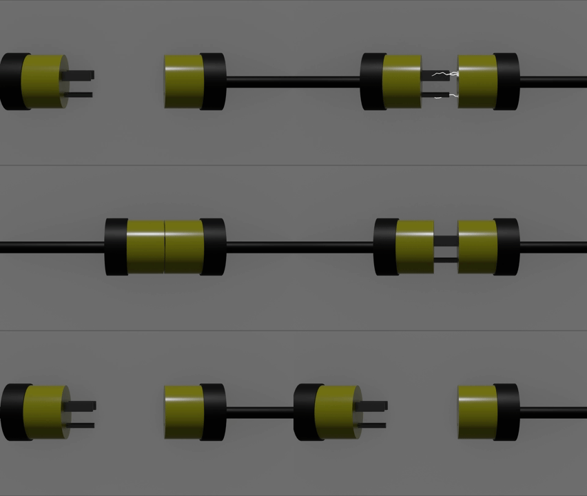
One method that stands out in the MIL-DTL-22992 is the Arc Rupture test. Put simply, connectors undergo 50 continuous mating/demating cycles while carrying test current. As the connector ends are separated and/or connected, the distance between mating electrical points varies. The closer each pin and socket are to one another, the more likely the air between the two will break down into an electrical arcing event (Picture the small electrical arcs that sometimes occur when plugging a device into a wall outlet, particularly when the device’s switch is in the “ON” position). Electrical arcs, even relatively small ones (in AIR6982 these are called “high impedance arcs” or “series arcs”), can result in equipment damage that will affect reliable functionality. The intent is to identify electrical and mechanical damage resulting from electrical arcs that would prevent the mating/demating of the connector ends by normal means.
There is no method in MIL-DTL-38999 with the same performance or intent as the Arc Rupture test of MIL-DTL-22992. Rather, the 38999 connectors are built with more robust coupling mechanisms and require more mechanical testing (Coupling and Uncoupling Torque, Durability, External Bending Moment, Bayonet Coupling Pin strength, etc.) to the extent that accidental demating of powered connectors is not considered a risk.
Conclusion
Ultimately, the planned testing conditions for EWIS components should represent the anticipated vehicle operations and environment. This may mean making changes to standard values or referencing any number of different standards. It is important to explore many testing options to develop a comprehensive qualification plan and ensure sufficient safety in the final aircraft design.