
Basics of Connectors
Circular connectors have been a part of the aircraft industry for nearly 90 years. Clearly, because of this long history, many lessons have been learned on the construction and use of these connectors. But before anyone can really consider how to use the connector, there are basics that must be understood. This article reviews some of the basics of circular connectors and it should also be useful as a connector type reference sheet.
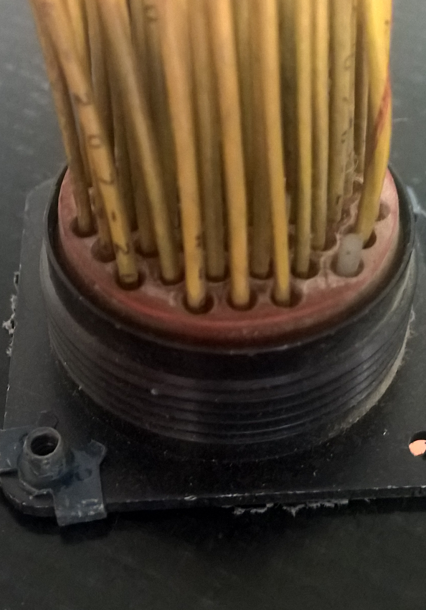
The MIL-DTL-38999 standard has been around for many years (currently in revision M), and because of the need to support both existing platform and new technologies, the standard is fairly lengthy. Given the wide range of connectors type and configurations covered in the standard, one would expect the standard to be two or more documents.
At the start of the MIL-DTL-38999, there is an identification of four series classes for the connectors specified in the document. On first pass, these connector designations may appear to be the same, but there are slight differences. The key differences are highlighted and should help to clarify some of the confusion.
|
Series |
Description |
|
Series I |
This series of connector is designed for use where a quick disconnect coupling system is required for blind mating or other mating problem areas. As part of the design, the coupling and contacts are designed to endure high-vibration environmental conditions and are suitable for severe wind and moisture problem (SWAMP) areas. |
|
Series II |
The Series II connector is designed for use in areas not subjected to high vibration or SWAMP conditions. These connectors have a smaller profile and weight less than Series I connectors. Use of these is ideal where space or weight is at a premium. Note that the Series II connectors are not scoop-proof. |
|
Series III |
Series III connectors are designed for high vibration, elevated temperatures, and SWAMP area use. The best performing plating systems to prevent corrosion from salt spray are found on Series III and IV connectors. |
|
Series IV |
The Series IV connectors are designed for use where a quick disconnect coupling system is required. The connectors are also rated for vibration and SWAMP areas. |
A scoop proof connector is one where it is not possible to damage the contacts while separating a mated pair. The connector shell is designed to require retraction before radial movement is possible.
Plating, Temperature, and Corrosion
There are six finishes for MIL-DTL-38999 connectors, each with their own positives and drawbacks. As a starting point, it is important to know the operational temperature range. An important item to note from the following table is that not all platings are the same. For example, The Finish code ‘M’ of electroless or electrodeposited nickel has a salt spray requirement of 2000 hours, whereas the salt spray requirement for other electrodeposited nickel finishes can be as low as 48 hours.
|
Class Code or Finish Code |
Series |
Description (finish or surface treatment) |
Shell material |
Salt spray (hours) |
Upper Temp |
Electrically Conductive Shell-to-shell Conductivity (millivolts) |
|
A |
I & II |
Cadmium over nickel, light gold |
AL |
48 |
150°C |
Yes (2.5) |
|
B |
I & II |
Cadmium over nickel, olive-drab |
AL |
96/500 |
175°C |
Yes (2.5) |
|
C |
I & II |
Anodic, black |
AL |
48/500 |
200°C |
No (N/A) |
|
D |
I & II |
Tin (see 3.3.1.3) |
CRS |
24 |
150°C |
Yes (10) |
|
E |
I & II |
Passivate |
SST |
48/500 |
200°C |
Yes (50) |
|
F |
All |
Electroless nickel |
AL |
48 |
200°C |
Yes (1) |
|
G |
All |
Electroless nickel |
AL |
48 |
200°C |
Yes (1) |
|
H |
III & IV |
Passivate |
SST |
500 |
200°C |
Yes (10) |
|
J |
III & IV |
Cadmium over nickel, olive-drab |
C |
2000 |
175°C |
Yes (3) |
|
K |
III & IV |
Passivate |
SST |
500 |
200°C |
Yes (10) |
|
L |
III & IV |
Electrodeposited nickel |
SST |
500 |
200°C |
Yes (1) |
|
M |
III & IV |
Electroless or electrodeposited nickel |
C |
2000 |
200°C |
Yes (3) |
|
N |
All |
Electrodeposited nickel |
SST |
48 |
200°C |
Yes (1) |
|
R |
All |
Electroless nickel |
AL |
96 |
200°C |
Yes (1) |
|
S |
III & IV |
Electrodeposited nickel |
SST |
48 |
200°C |
Yes (1) |
|
T |
All |
Nickel fluorocarbon polymer |
AL |
500 |
175°C |
Yes (2.5) |
|
U |
All |
Cadmium over nickel, light gold |
AL |
96 |
175°C |
Yes (2.5) |
|
W |
III & IV |
Cadmium over nickel, olive-drab |
AL |
500 |
175°C |
Yes (2.5) |
|
X |
All |
Cadmium over nickel, olive-drab |
AL |
1000 |
175°C |
Yes (2.5) |
|
Y |
III & IV |
Passivate |
SST |
500 |
200°C |
Yes (10) |
|
Z |
All |
Zinc nickel |
AL |
500 |
175°C |
Yes (2.5) |
- Al – Aluminum
- CRS – Corrosion Resistance Steel
- SST- Stainless Steel
- C – Composite
Unlike the salt spray requirement, the upper-temperature limit for these platings remains constant regardless of the shell material or the series type.
Up Next
In the next article, we will review each type of plating style and how it might be best used in aircraft systems. Also covered will be some of tests used to qualify and set benchmarks on connector performance. If you are looking for connector testing, Lectromec’s test listing covers a wide range of those necessary for comparison, qualification, and performance verification. We are here to help.