Key Takeaways
- The decision of whether to fully complete cable harness assembly before or during installation on aircraft is non-trivial and requires multiple engineering perspectives.
- Beginning installation with incomplete harnesses is a more flexible approach but often difficult due to the space and visibility limitations of working on-aircraft.
- Completing harness construction prior to installation makes the actual construction process easier, but requires a high level of confidence in the accuracy of the design on paper.
Those that have ever had to crawl around an aircraft know the difficulty of any maintenance activity. Those tasks that require precision are made much worse as being able to read, align, and fit tools into some areas can be both frustrating and take far more time than they would in a shop.
In this article, we explore the tradeoffs for completing work on an aircraft versus completing work prior to installation and delivering it to the vehicle.
What is a Completed Harness?
A completed harness is one where:
- The wires/cables are all cut to a specified length,
- The ends are stripped and terminated in accordance with the build requirements,
- The connectors and backshells/strain relief are attached,
- Cable shielding is properly grounded,
- The cables are grouped and tied together at specified locations to account for harness branching,
- Secondary protection is applied (if applicable),
- Critical clamp markers are added, and
- End point identification and harness identification heat shrink is attached.
This completed harness, in a sense, is a line-replaceable unit (LRU) and can be directly installed on a vehicle. While the harness still must be routed on the vehicle and attached to primary support locations, such a harness does not require length adjustments or changes to be made as part of the final installation.
Incomplete Harness Installation
There are several benefits for installing an incomplete harness and seeking to complete it on the vehicle. The following are several justifications for this design/build approach for equipment/vehicles.
The harness can be cut to length to fit the final design. This option appeals to those who do not have a final design and/or do not have a high degree of confidence in the tolerances within the design drawings. This may be for low volume applications or those in the prototype stage. Those who stand to gain the most from this approach are those with rapidly changing designs and who need to avoid being locked into a pre-defined harness configuration. This allows for adaptability with the final assembly being adjusted to fit the aircraft needs at the time of installation.
-
By completing the final assembly on aircraft, it is possible to feed the wire harnesses through tight areas that the final connectors may not be able to pass through. This is certainly a preferred option for aircraft structures teams as it helps to reduce the total size of holes cut through structure.
There is practical consideration here for limiting that hole size as much as possible. For example, consider a MIL38999 connector for 7x 20 AWG wires; a MS38999 option for this might be a shell size 11 with an OD (outer diameter) of 0.859 inches. Compare this with a maximum OD of the representative harness of 0.18 inches (not including spot ties), there are a lot of places an unterminated harness can fit that would not accommodate a connector.
Joining of multiple harnesses. The complexity of aircraft wiring harnesses is not something to be brushed aside. A lot of work goes into coming up with the ideal routing to meet the needs of both the equipment that is being supported and the practical physical limitation of where the wiring can be placed. Building wire harnesses one group at a time and then joining them on the aircraft may be more practical for several reasons which include:
- Limit the overall weight of the wire harness. The wire harness can be very heavy and hard to move. The heavier the harness, the more that the installers will have to struggle and potentially damage the wire harness during installation. By limiting this weight to practical limits of usability, it is less likely to be subjected to, encounter, or incur damage during the installation.
- Complexity. By limiting the number of endpoints within a wire harness, the wire harness fabrication becomes easier. It is more likely to find any issues during the fabrication, and it is potentially easier to replace and/or repair if problems arise.
Drawbacks
As with any engineering approach, there are drawbacks to harness completion on aircraft. These drawbacks go beyond the simple impact of increased installation time, though that factor should not be ignored. The following are potential drawbacks for on-aircraft harness completion.
Time on aircraft for installation. By waiting for the installation and connectorization on aircraft, the time necessary to install a single harness will increase based on the complexity of the harness to be installed. Certainly, a connector with 120 pins takes more time to complete than a connector with just four pins. On top of that, any additional assembly efforts such as stripping, shield preparation, soldering, etc. will add to the total time.
Each action performed on aircraft is potentially a blocking activity for other actions in the same area. For example, an installer team seeking to place an LRU may not have access to an area if another team is routing wires behind the same panel.
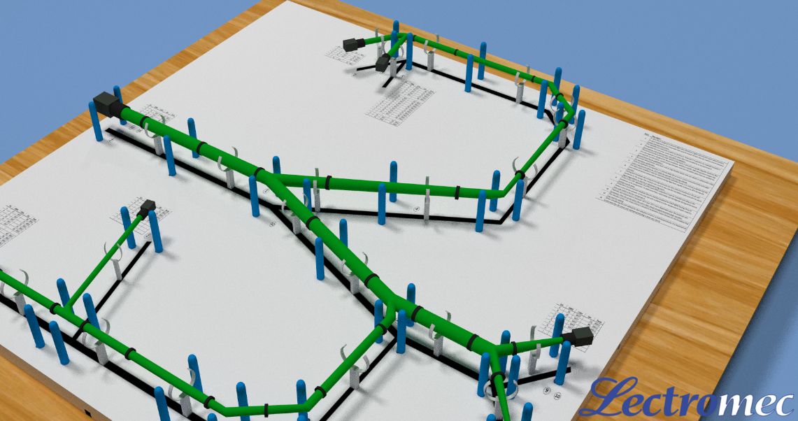
Form boards are used to map out and construct harnesses prior to installation on the aircraft.
Ease of Access. When the harness is being manufactured on a form board, there is a well-lit area with plenty of room and accessibility to the harness for manipulation. When the harness is installed in the aircraft, the available space around the harness is likely diminished, making it more difficult to perform any harness completion action. Any sort of soldering activity can be quite cumbersome and may even be risky when performed on the fueled aircraft. Furthermore, this lack of space inhibits a thorough final product inspection.
Complexity of verification. When the harness is in the shop, end-to-end resistance checks, functional checks, visual inspections, and any other performance checks can be done with relative ease. With the easily accessible harness attaching to benchtop harness testers is straightforward; there is no concern that the harness is terminated on the other side of the vehicle meaning the need for long connection cables to automatic wire test systems.
FOD. The termination of a wire/cable is a process that can generate a great deal of Foreign Object Debris (FOD). For example, terminating a cable requires:
- Cutting the cable/wire to length (Cable FOD)
- Removing jacket to pull back the shield (jacket FOD and potentially broken shield conductor FOD)
- Strip the cable’s component wire (insulation FOD and potentially cut conductor strands)
- Crimping contacts onto conductor (potential for FOD – the container in which the contacts were stored)
- Inserting the contacts into the connector (potential for FOD – the container/bag in which the connector was stored)
- Attach the shield to a solder sleeve and attach to connector backshell (potential for FOD – trimmed solder sleeve jumper wire length)
Each of these steps can create FOD. Proper area preparation, harness setup, and personnel training will help to reduce the FOD, but even with the most diligent of processes and personnel, across an entire aircraft, it is unavoidable that FOD will be generated.
Termination protection. Historically, the last 24 inches of any wire harness are the most prone to failure with the termination being the weakest link in the chain. At the termination, the change from a flexible wire to the stiff contacts may be stressed during transport and/or installation.
Installing a Complete Harness
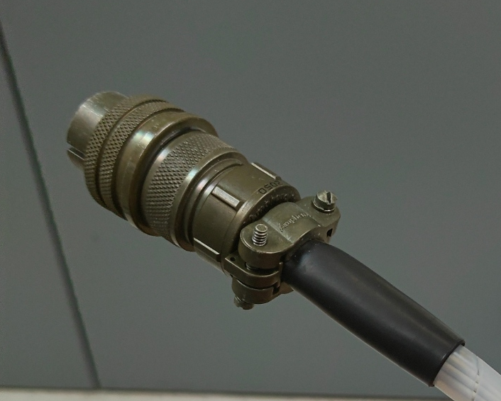
Wiring and assembly of a connector is a much easier task off-aircraft where limitations on space and lighting are not of concern.
Rather than have a section of this article devoted to identifying counterpoints to the incomplete harness drawbacks, it is important to recognize that completed harnesses are not the ideal solution for every application. Streamlined, vetted, repeatable applications can gain from delivering to the aircraft completed, connectorized harnesses. Determining how far into a vehicle’s development incomplete harnesses remain is a decision involving several engineering disciplines.
Conclusion
There can never be a one-size-fits-all solution for EWIS, and the complexity of wire harness installation needs only adds to these challenges. The benefits of installing a complete harness on aircraft can include having a fully tested assembly ready for use, speed of insulation, and final part quality control. As discussed above, the benefits of completing the harness on aircraft include fitting through tight space, limiting harness weight, and accommodations for aircraft variability with spare length to support alternative routing requirements.
For those seeking support in their EWIS design, assessment, testing, and certification, contact Lectromec.

Michael Traskos
President, Lectromec
michael.traskos@lectromec.comMichael has been involved in wire degradation and failure assessments for more than two decades. He has worked on dozens of projects assessing the reliability and qualification of EWIS components. Michael is an FAA DER with a delegated authority covering EWIS certification and the former chairman of the SAE AE-8A EWIS installation committee.