Key Takeaways
- The ASTM F3309 provides a simplified qualitative method for the evaluation of small aircraft safety.
- Each failure condition under evaluation must meet the minimum probability required for its level of severity.
- Negligible and minor failure conditions only require detailed appraisals to prove the probability of failure, whereas more severe failure conditions require additional qualitative safety evaluation.
Introduction
Aircraft safety requirements vary depending on the size of the aircraft. Typically, larger aircraft have stricter requirements as a catastrophic failure in large aircraft has the potential for a much larger loss of life than that of small aircraft which hold far fewer passengers. The ASTM F3309 provides a simplified qualitative approach to evaluate the safety of small aircraft.
Safety Goals
The ASTM F3309 covers simplified qualitative assessment of the safety of small aircraft; in particular, Level 1 and Level 2 aircraft. Level 1 aircraft accommodate zero to one passengers and Level 2 aircraft accommodate two to six passengers. The primary goals are to ensure that each potential failure condition adheres to the appropriate probability and that the installation of the system under analysis does not create opportunities for additional hazards.
The following table identifies severity of failure conditions and the required minimum probability associated with each. This is the cornerstone of the ASTM F3309; all analytical methods pertain to the verification of the items in this table.
Negligible |
N/A |
Required |
Not Required |
Minor |
Probable |
Required |
Not Required |
Major |
Remote |
Required |
Required only on Level 2 Aircraft |
Hazardous |
Extremely Remote |
Required |
Required |
Catastrophic |
Extremely Improbable |
Required |
Required |
A common means of validating these criteria is a detailed FHA (Functional Hazard Assessment) (More info on this can be found in SAE ARP4761), but this article focuses primarily on the simpler means of safety analysis discussed in the ASTM F3309.
We will begin by reviewing the methods of safety analysis covered in the ASTM F3309
System Appraisals:
Qualifying small aircraft must perform both a design appraisal and an installation appraisal for approval prior to the installation of all systems and equipment.
Design Appraisal:
The ASTM F3309 identifies the design appraisal as: “a qualitative appraisal of the integrity and safety of the system design.” The appraisal should elaborate on the integrity and safety of the design under evaluation in a straightforward, easy-to-follow way, including discussion of component selection/ qualification, system independence, system separation, and redundancy. Supporting evidence for this appraisal may include system design documents such as architecture diagrams, block diagrams, and detailed FHA tables.
Installation Appraisal:
The ASTM F3309 identifies the installation appraisal as: “a qualitative appraisal of the integrity and safety of the installation.” This appraisal may include installation drawings, equipment installation requirements, and relevant analyses to support the argument of the installation’s safety. The appraisal must address potential interference with other systems during installation and maintenance as well as physical and functional separation between components. It is imperative to consider potential system failure and how it may impact the independence of nearby systems based on the means or location of installation; for instance, one must recognize the probability of an electrical arcing event causing physical or electrical damage to nearby components that may otherwise have been functionally independent.
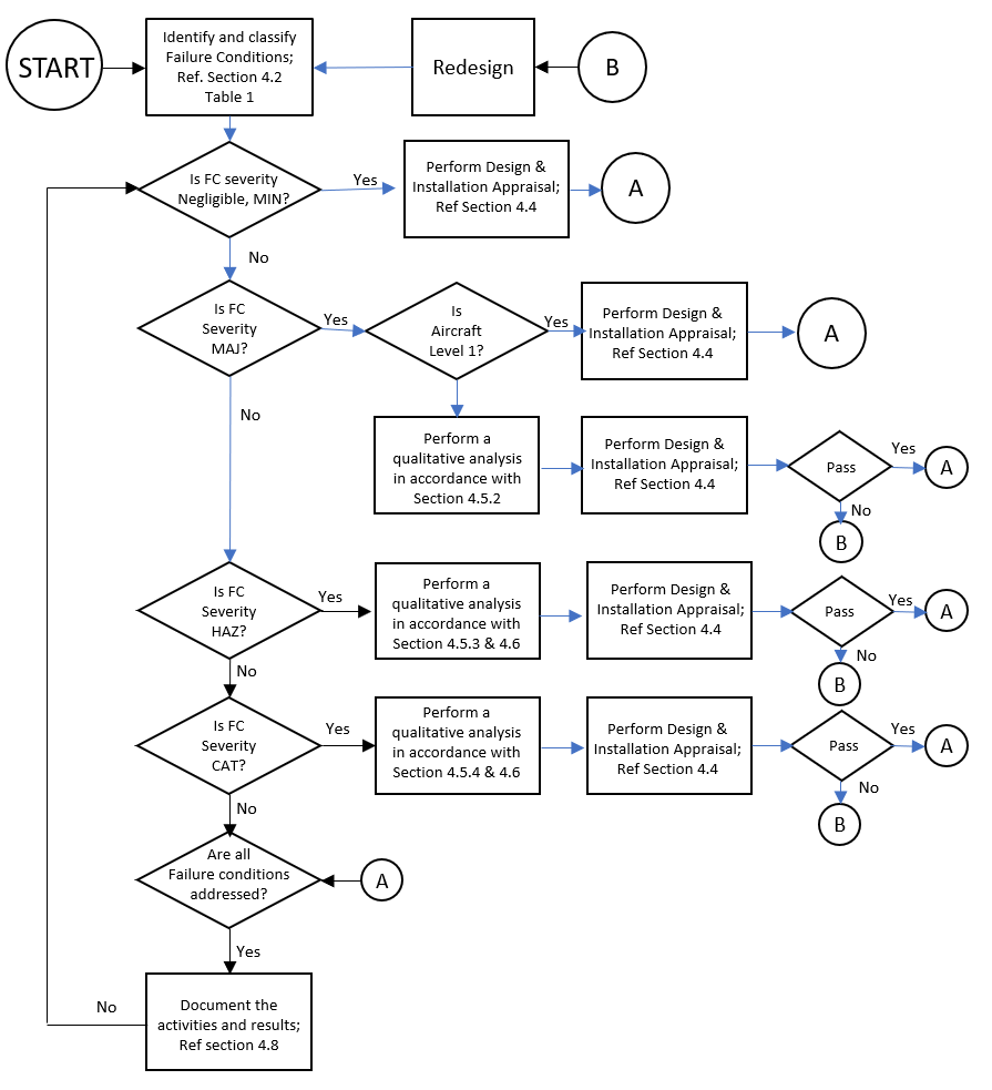
The flowchart shown here is taken directly from the ASTM F3309 document and depicts the process of the safety assessment.
According to the ASTM F3309, the design and installation appraisals are sufficient analyses for the requirements of Negligible, Minor, and Major failure conditions, however this does not hold true in the case of Level 2 aircraft.
Qualitative Analysis for Failure Conditions
Hazardous and catastrophic failure conditions are the most severe conditions to consider as they have the potential to result in fatality. For each of these severe failure conditions under analysis, the method used must identify the probability of said condition to meet the respective requirements. As mentioned in the table above, hazardous failure conditions must be shown to be extremely remote and catastrophic failures must be shown to be extremely improbable. (These methods may also be applied when evaluating Major failure conditions to be remote on level 2 aircraft).
Similarity Argument:
The safety of a particular system on a small aircraft may be confirmed by a similarity argument where applicable. A similarity argument references a previously approved design/ installation and shows that the proposed design is adequately similar in regard to the safety and failure probability. If a previous similar aircraft was already shown to have a very improbable likelihood of a catastrophic failure, it can be argued that the design under analysis has that same probability.
Multiple/ Single System Failure Conditions:
For new or unique aircraft design, a similarity argument may not be applicable or available. Such circumstances call for further qualitative assessment of the systems’ potential failure conditions to ensure the safety guidelines are adhered to. There are two primary types of failure conditions assessed in this method that may cause a system’s “loss of function”.
- Multiple System Failure Conditions – Many systems integral to the basic function of an aircraft have redundancy, that is two or more independent systems capable of performing the same function. When evaluating the failure conditions on such systems one must prove the redundancy of the function. The individual systems of identical function must be shown to, in fact, perform identical functions in the case that one encounters a failure during operation. These systems must be shown to be both functionally and physically independent. Such independence can be shown through a common mode analysis; this analysis is used to show that the “independent” systems are truly independent – ensure they do not share any common means of failure (common power supply, ground return, etc.) and that installation or maintenance does not affect the independence of these systems.
- Single System Failure Conditions – If a single failure can cause the failure condition then the system should be proven to have a probability of failure equal to that of the condition under evaluation.
Catastrophic failure conditions must only be possible via a multiple system failure.
Conclusion
Though small aircraft safety requirements are more lenient than those for large passenger aircraft, it is important to identify and adhere to the appropriate safety regulations when designing and building any aircraft. For more information regarding safety assessments of your small aircraft, contact Lectromec today!

Laura Wishart
Engineer, Lectromec
laura.wishart@lectromec.comLaura has been with Lectromec since 2019 and has been a key contributor on projects involving testing of EWIS/fuel system failure modes, the impact of poor installation practices on EWIS longevity, and wire/cable certification testing. Her knowledge and attention to detail ensure consistent delivery of accurate test results from Lectromec’s lab.