Key Takeaways
- Additive manufacturing (AM), commonly known as 3D printing, is emerging as a promising method to produce certain EWIS components.
- With the current state of AM technology, it is possible for modern 3D printers to produce high-quality connector bodies, replacing what would traditionally be custom injection-molded parts.
- Additive processes involve an unusually high number of process parameters and variables that must be defined and reliably repeatable.
Introduction
Electrical Wiring Interconnection System (EWIS) is the amalgamation of wires, cables, connectors, and support hardware that connect aircraft components. For most aircraft, the bulk of these standardized parts are produced by component manufacturers and qualified by the OEM and/or independent body (e.g., NAVAIR QPL). Additive manufacturing (AM), commonly known as 3D printing, is emerging as a promising method to produce certain EWIS components. This technology offers design freedom to create complex, lightweight structures and the ability to manufacture low-volume or custom parts without expensive tooling. In this article, we explore which EWIS parts can be built with AM, review FAA guidance on qualifying AM parts, discuss current process control standards for AM, and examine the challenges identified with 3D-printed aerospace components.
EWIS Components Suitable for Additive Manufacturing
A 3D-printed connector mounting holder for an aerospace wiring harness is an example of how additive manufacturing can produce custom EWIS hardware. The holder shown here was designed by TE Connectivity for their D369 electrical connectors at the request of an aircraft manufacturer, and it had to be printed from a flame-retardant polymer with high accuracy (± 0.002 inch) to meet aerospace requirements. This accuracy and repeatability are necessary for connectors mating reliably and ensuring that environmental seals hold. Furthermore, it is important to note that the printed connector bodies are fitted with standard metal pins or contacts after print as the AM process does not work well for complex conductive parts (e.g., plated metals).
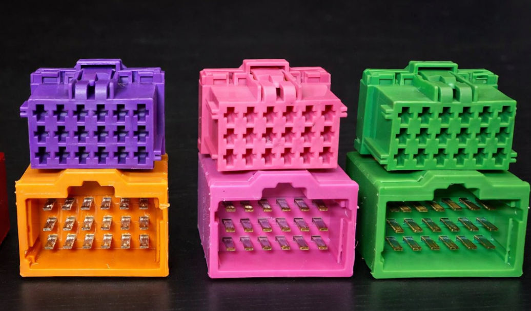
3D printing many types of EWIS parts is now possible. Here is an example of 3D-printed electrical connectors. Note that the contacts are added after the print.
Connectors and connector housings are prime candidates for AM because they are often made of high-performance plastics and require complex shapes to accommodate multiple pins. This flexibility is especially useful for prototyping new wiring systems or producing small batches of specialized connectors without expensive tooling. With the current state of AM technology, it is possible for modern 3D printers to produce high-quality connector bodies, replacing what would traditionally be custom injection-molded parts.
Beyond connectors, many wire harness supports and routing components can be produced with additive methods. 3D-printed clips, clamps, and brackets can be used to secure wire bundles and route cables along aircraft structures. These parts tend to be small and geometrically intricate, all of which are attributes well suited to AM. For example, lightweight cable clamps or spacers can be topology-optimized (minimized weight while maintaining strength) and then printed in durable polymer or even metal. Using 3D printing for such parts can reduce assembly complexity and allow designs that fit the aircraft’s contours more tightly than COTS parts.
Going further, wire harness manufacturing can be aided with AM parts by creating custom assembly fixtures and tooling to improve efficiency. Jigs, holders, and test fixtures can be created to aid in wiring assembly and testing (something Lectromec has been doing in our lab to support testing for almost a decade). While the printed tools are not flight hardware, they can offer a means to simplify production when designs change.
It is important to note that not every EWIS element is easily produced by AM. The wires themselves (made of tin/nickel/silver plated copper or aluminum conductors) are not typically 3D-printed. Similarly, standard electrical contacts, terminals, and backshells often have decades of qualification data behind them and are made via precision machining or molding. Additive manufacturing in EWIS is thus currently focused on non-electrical structural parts of the wiring system. Airbus reported its first 3D printing metal printed cabin brackets and other non-critical parts in 2017 on their A320neo and A350 aircraft.
FAA Guidance on Qualification of AM Parts
Introducing additively manufactured parts into certified aerospace systems requires demonstrating that these parts are as safe and reliable as traditionally made ones. The Federal Aviation Administration (FAA) has been actively developing policies to guide the certification (qualification) of AM parts. One example is FAA Advisory Circular AC 33.15-3 (issued June 2023), which describes an acceptable means of compliance for aircraft engine parts made by powder bed fusion additive manufacturing. While AC 33.15-3 is specific to engines (14 CFR Part 33) and metal powder-bed processes, it provides a template for how applicants can demonstrate an AM part meets regulatory requirements. Further, the AC addresses topics like material characterization, process validation, inspection, and static and fatigue strength substantiation for 3D-printed engine components. This indicates the FAA’s general approach: an AM part must be backed by extensive data proving its material properties and performance under all conditions required by the regulations.
Those that have used 3D printers for an extended period will see a lot of hard learned lessons covered. Source: FAA AC 33.15-3
For other types of parts (such as EWIS components under aircraft certification rules), the FAA currently handles qualification on a case-by-case basis. Certification applicants proposing AM parts often engage with the FAA early to define the certification plan. In practice, the FAA may use issue papers or Applicant-Specific Guidance Memoranda (ASGM) to address the unique considerations of a 3D-printed part. These project-specific guidance documents ensure the FAA and the applicant agree on critical aspects like the part’s function, the novel materials or processes being used, how the process will be controlled, and what testing is needed.
Notably, the FAA’s guidance memos typically focus on process control and validation methods as part of the means of compliance. This means an applicant must explain how they will consistently produce parts that meet specifications and how they will validate the AM process (through testing coupons, analyzing microstructure, etc.). The FAA has stated that existing rules (e.g. requirements for materials, fabrication methods, strength, and safety) still apply – there are no “special” easier rules for AM. Instead, additional scrutiny is applied via policy memos and issue papers to make sure novel AM methods are rigorously qualified before acceptance.
Process Controls for Additive Manufacturing
One of the critical aspects of qualifying AM parts is demonstrating robust process control. Unlike traditional manufacturing, additive processes involve an unusually high number of process parameters and variables. For example, a laser powder bed fusion (PBF) process may have over 100 adjustable parameters that can affect the final part. Key process variables include things like laser power and scan speed, layer thickness, hatch spacing and scan patterns, the build chamber atmosphere and temperature, and powder feed rate. Current FAA and industry guidance emphasize that the manufacturer must identify and control the parameters that significantly influence part quality. This can mean process validation, examining product quality at the minimum and maximum range of these key parameters. In AC 33.15-3 for engine parts, the FAA explicitly states that any process parameters impacting the chemical, metallurgical, dimensional, or mechanical properties of the part should be treated as critical variables, with specified allowable ranges and monitoring to ensure they stay within those limits.
A cornerstone of process control is a well-defined process specification. The FAA’s general certification policies (e.g. FAA Order 8110.4C) require that applicants have approved process specifications for any fabrication method that needs close control. In practice, this means an AM process spec should detail everything such as the process, the materials and machines used, environmental controls (for example, humidity or oxygen levels for powder), inspection methods, acceptance criteria, and records of process qualification. By imposing a rigorous specification and control plan, the goal is to consistently produce conforming parts from the AM process, part after part, batch after batch.
Conclusion
Additive manufacturing of EWIS components is an exciting development at the intersection of modern 3D printing technology and the stringent world of aircraft wiring systems. Parts like connector housings, wire clamps, and custom harness brackets can now be 3D-printed with designs optimized for weight and performance, produced on-demand without special tooling. The FAA has signaled openness to these innovations, provided that companies thoroughly qualify the AM parts under existing regulations. This means proving material properties, ensuring consistent production through strict process controls, and validating each part’s performance (from mechanical strength to flammability) with no compromise.
Current guidance from the FAA (such as ACs and policy memos) underscores the need for robust process specifications and highlights that quality must be built into the additive process just as it is for conventional methods. Early use-cases in aviation have shown both the feasibility and the challenges of AM. While numerous printed parts are already flying (especially less critical ones), the industry has faced hurdles with consistency, inspection, and material behavior that are being overcome through ongoing research and collaboration.
For those looking to test their AM or non-AM EWIS parts, contact Lectromec. Our ISO 17025:2017 accredited lab is ready to help.

Michael Traskos
President, Lectromec
michael.traskos@lectromec.comMichael has been involved in the field of EWIS for more than two decades and has worked on a wide range of projects from basic component testing, aircraft certification, and remaining service life assessments. Michael is an FAA DER with a delegated authority covering EWIS certification, the former chairman of the SAE AE-8A EWIS installation committee, and current vice chairman of the SAE AE-8D Wire and Cable standards committee.