Key Takeaways
- A new version of MIL-HDBK-522, a US military reference handbook which offers guidelines for electrical wiring interconnection systems (EWIS) inspection of military aircraft, was released on May 11, 2021.
- Guidelines covering components not addressed in previous revisions have been included in the most recent version. These include inspections of SAE AS34591 connectors, cable lacing fasteners, and spring band shield terminations.
- A variety of changes have been made to existing sections of MIL-HDBK-522 regarding the specifics of the inspections, but each guideline maintains the principals of the previous revisions.
Introduction
No matter how much documentation exists, there will always be a need for updated guidance on the sustainment of aircraft systems. While it might not look like it, there are constantly new products being installed onto aircraft that require different maintenance techniques than the previous generation of components. One of the references that has been helpful to maintainers over the last decade has been the US Navy’s wiring systems maintenance handbook, MIL-HDBK-522.
Briefly, MIL-HDBK-522 is a US military reference handbook which offers guidelines for electrical wiring interconnection systems (EWIS) inspection of military aircraft. While not an official military requirement or standard, the “MIL-HDBK” designation is intended to be used for guidance. Though intended for military applications, the guidelines are applicable when performing EWIS inspections on any aircraft.
A new version (Revision C) of MIL-HDBK-522 was released on May 11, 2021. This article examines many of the changes made between Revision B and Revision C. The previous revision (Revision B) was released on November 20, 2018 and discussed here.
Updated Definitions
Only three defined terms within the handbook had their definitions updated in the new version. The terms “lacing tape” and “safety wire” were both updated to include other names they are identified as in application: “spot tie” and “lockwire”, respectively.
The term “harness” has been updated to include “any number of wires, electrical/optical cables, and/or groups and their terminations” within an assembly. The definition in Revision C also explicitly includes both open and protected harnesses.
Additional Guidelines
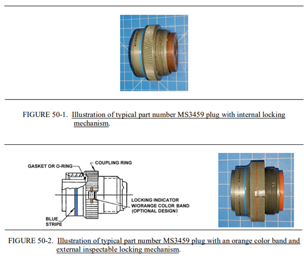
Figures 50-1 and 50-2 from MIL-HDBK-522 show examples of part number MS3459 connectors.
Perhaps most notable in the new revision of MIL-HDBK-522 is the addition of three new guidelines:
- Guideline 50 – SAE AS34591 Connector Mated Inspection
- Guideline 51 – Cable Lacing Fastener Inspection
- Guideline 52 – Spring Band Shield Termination Inspection
Guideline 50 specifically applies to connectors with part number MS3459 which are regulated by SAE AS34591. This guideline shares many similarities with Guideline 5 – Connector Mating Inspection, but specifically addresses the self-locking mechanism of the MS3459 connector and the means of ensuring that it is correctly mated. To quote directly from the standard, “Some manufacturers’ coupling ring designs use an internal locking device which is not inspectable (see figure 50-1). Other manufacturer’s designs include an orange color band indicator identifying an externally inspectable locking mechanism (see figure 50-2).”
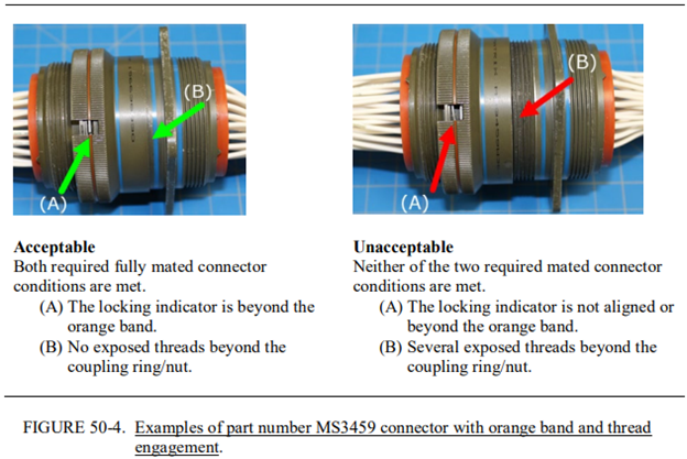
Example of proper and improper mating of part number MS3459 connectors.
The orange band connectors are inspected for two conditions required for proper mating:
- The locking indicator must be even with or beyond the orange band, and
- Coupling threads must not be exposed beyond the coupling ring/nut.
Guidelines 51 and 52 discuss the inspection of select components that were not covered in Revision B: cable lacing fasteners and spring band shield terminations, respectively. Each of these newly incorporated components is given a set of inspection guidelines in Revision C.
Cable Lacing Fasteners
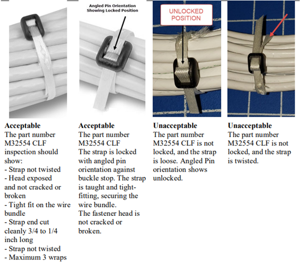
Examples of acceptable and unacceptable applications of cable lacing fasteners.
The cable lacing fasteners covered by Guideline 51 are part number M32554. The fasteners should be installed such that they are snug around the wire bundle with no twisting of the strap, no cracks or damage to the fastener head, and no more than three wraps around the bundle. The fastener head should be clearly exposed for ease of inspection with the strap locked properly into place. The exposed lacing end should be cut approximately 0.5 inch from the fastener head.
Spring Bands
The spring band shield terminations covered by Guideline 52 are part number M32628/01-XX and are governed by standards MIL-DTL-32628 and MIL-DTL-32628/1. The spring bands covered in this guideline are capable of installation and removal by hand without the use of special tools or equipment, but are not always the appropriate choice for shield termination: “As an EWIS shield termination device, the reusable part number M32628/01 spring band is for use with or on part number M85049/82 through /90 connector backshells for EMI (Electromagnetic Interference)/RFI (Radio Frequency Interference) applications.” Part numbers outside this range are not compatible with the M32628/01 spring band.
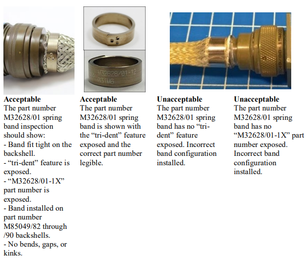
Examples of acceptable and unacceptable applications of spring band.
Inspection should verify that the spring band is used in the appropriate application, is fit closely and tightly to the cable shield, no gaps, bends or kinks are present, and that the “tri-dent” closing feature (see image below) and part identification number are exposed and clearly visible. When these criteria are not met, the spring band should be replaced.
Updates to Existing Guidelines
Plenty of changes have been applied to existing guidelines within MIL-HDBK-522 which affect the application, method, or value of the item under inspection. This section highlights select changes in the latest revision.
GL1: Introduction and Inspection Techniques
Guideline 1 discusses general methods of inspection which primarily remain consistent between the two revisions with only minor differences. Upon discovering discrepancies with the handbook, Revision B calls for immediate correction, whereas Revision C calls for documentation of each discrepancy. Additionally, a minor change in inspection methodology is implemented in Revision C, allowing for the use of LED bulbs as a secondary lighting source where only incandescent bulbs were approved in revision B.
GL2: Incoming/ Receiving Wire Inspection
Guideline 2 covers inspection performed on wire upon receipt of product. One part of this inspection is the verification of ID marking on the wire. The wire part number and Cage code should be identified on the length of the wire in intervals of 12 inches according to revision B. Revision C updates this interval to a length of 6 to 60 inches with no marking required on 26AWG wire or smaller. Guideline 2 also includes the addition of an inspection for signs of corrosion on fluoropolymer-insulated wire, namely white or green discoloration, entirely new to Revision C.
GL9: Mechanical Stripping Wire Inspection
Guideline 9, in both B and C revisions, recommends that wire stands that have become unwound should be retwisted to the appropriate shape. Revision B allows for the use of pliers if the individual stands are too large to be twisted by hand, but Revision C only recommends re-twisting the strands by hand.
GL13: Cable Harness Covering or Protection Inspection
Guideline 13 receives further elaboration in Revision C from the previous version. Where Revision B suggests covering sharp edges with an appropriate grommet or Teflon sheet, Revision C expands on this, suggesting rerouting of the wire bundle and securing it with a minimum 1/2 inch clearance. Revision C goes on to only recommend the installation of chafe protection in areas where repositioning/rerouting alone will not suffice.
GL15: Wire/ Harness Clearance Inspection
Guideline 15 applies to wire and wire harness positioning clearance, citing minimum clearance requirements for wire/wire harnesses routed near structure, fluid lines, electronic equipment, etc. Revision C of the handbook expands on the minimum requirements identified in revision B, providing guidance for repositioning harnesses that are too close to structure, distinguishing between requirements for clearance from fluid lines and flammable fluid lines, and identifying “rigid” separation for maintaining adequate clearance during operation.
GL17: Lacing Tape Inspection
Revision C of the handbook introduces the acceptable use of black-colored lacing tape with the approved product ID per Guideline 17.
GL29/30/31: Heat Applied/ Cold Applied/ Heatless Splice Inspection
Guidelines 29, 30, and 31 all address inspection guidelines for splices. Revision B of the handbook lists several explicit items to look for that have been removed in Revision C. Revision C instead has compacted these sections and chosen to explicitly reference NAVAIR 01-1A-505 WP 014 00 for the specific information regarding the inspection of splices.
GL45: Grommet Inspection
Revision B, Guideline 45 recommends the use of grommets when a minimum 1/2 inch clearance cannot be maintained between wire and structure/equipment. The recommended minimum clearance is updated to 3/8 inch in Revision C.
New and Updated Figures
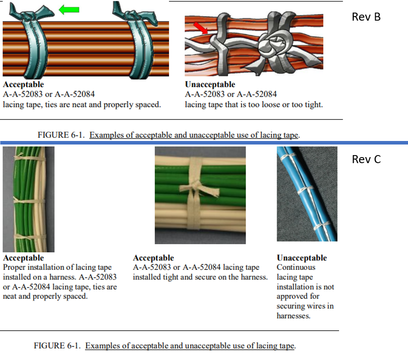
Figure 6-1 in Revision B (top) and Figure 6-1 in Revision C.
The figures associated with each guideline in MIL-HDBK-522 show drawn diagrams and photographs of acceptable and unacceptable examples of the relevant component(s) to the associated guideline. Between Revision B and Revision C thirteen (13) of the forty-nine (49) common guidelines have received additional or updated figures and three (3) guidelines have had figures removed. Adding to the figures already present in Revision B provides more clarity on what to look for in an inspection and covers more potential situations one may encounter in an inspection.
Conclusion
Between revisions B and C of MIL-HDBK-522 several changes have been implemented but generally, the principles represented remain the same. The handbook continues to provide a comprehensive guide for aircraft EWIS inspection that aims to maintain the safety and functionality of aircraft.
If you are looking for direct or training support on EWIS programs, Lectromec is here to help.

Laura Wishart
Engineer, Lectromec
laura.wishart@lectromec.comLaura has been with Lectromec since 2019 and has been a key contributor on projects involving testing of EWIS/fuel system failure modes, the impact of poor installation practices on EWIS longevity, and wire/cable certification testing. Her knowledge and attention to detail ensure consistent delivery of accurate test results from Lectromec’s lab.