Key Takeaways
- Critical Role of Contacts: Connector contacts are foundational to aerospace electrical systems, and their mechanical reliability is vital for sustained performance in harsh environments. Choosing high-quality AS39029 contacts helps ensure long-term connectivity.
- Engineered for Retention: AS39029 crimp contacts are secured by robust rear-release retention clips, providing high axial retention forces (on the order of dozens of pounds) to prevent contact back-out under stress.
- Vibration and Shock Resilience: The design of AS39029 pin-and-socket contacts (spring socket geometry, materials, and plating) maintains firm electrical contact even under intense vibration and shock. Stringent MIL-spec tests (vibration, shock, durability) verify that no momentary disconnections occur in aerospace conditions.
- Crimp Versus Solder Performance: Crimped contacts form gas-tight, strong joints with wires, offering high tensile strength and strain relief. Soldered contacts, while sometimes necessary, are mechanically less forgiving – solder joints can be brittle under vibration and require careful strain relief to avoid wire fatigue.
Contact Reliability Matters
Statistically, the most common location for wire issues is within 24 inches of a wire’s termination, and because of this, proper termination of wires is necessary to reduce the likelihood of failure. Ensuring high reliability requires a combination of selecting the right wire, connector, and the right contacts. Because the connector’s contacts are the carrier of electrical energy, ensuring connector contact reliability is critical for aerospace environments where vibration, shock, temperature extremes, and moisture are common stressors. For aerospace Electrical Wiring Interconnection System (EWIS) engineers, using contacts qualified to rigorous standards is a key part of designing robust systems.
Common Contacts
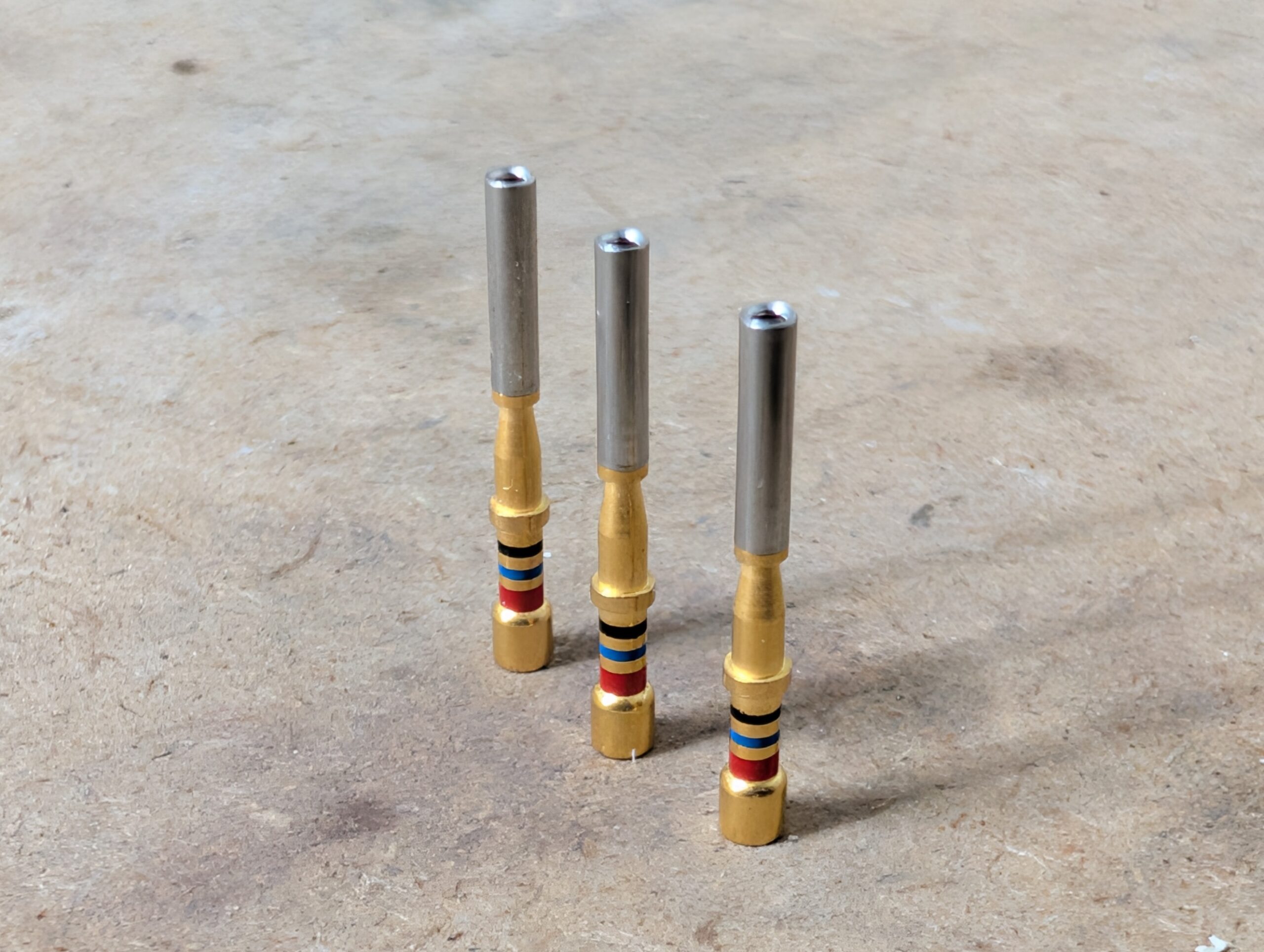
The AS39029 series (also known by the legacy MIL-C-39029 designation) defines removable electrical contacts used in many military/aerospace connectors (such as MIL-DTL-38999 circular connectors). These contacts come in two main termination styles:
- Crimp contacts which are crimped onto wire conductors and require specialized tooling, and
- Solder contacts which have a cup or well for soldering the wire.
When it comes to connector contacts, contact retention is the mechanism that keeps the contacts in place and secure in the connector housing. The AS39029 crimp contacts typically employ rear-release retention clips, there are some contacts in the AS39029 family that use front-release design, like the AS39029/1-/7 contacts, but they are more the exception than the rule. The design choice for rear-release contacts was for several reasons (there are many, but only a few are presented here):
- Contact removal occurs from the wire-entry (rear) side, so the mating interface (pin/socket) is protected from tool damage. Contact removal can require some finesse, and even with care, it is difficult to prevent contact mating surface damage during extraction.
- Rear removal prevents contact tines (especially on sockets) from being bent or overstressed during extraction. The crimped/soldered side of the contact also adds mechanical strength to support the extraction.
- Interaction with connectors is typically from the rear of the connector. Inserting the wire through the connector, terminating the wire, then pulling back through the connector is an unusual process.
- Rear-release contacts are compatible with environmental sealing grommets. Because of the design, front-release contacts and connectors require a different approach to sealing and are often less effective.
In the rear release contact designs, each contact is a machined pin or socket with a circumferential groove. A spring metal clip (often made of heat-treated beryllium copper) is embedded in the connector’s insulating insert. When the contact is inserted from the rear of the connector, the clip snaps into the contact’s groove, locking it into place. This mechanism provides strong axial retention: the contact cannot be pushed out from the rear or pulled out from the front unless the clip is intentionally released using the proper extraction tool. The result of the rear release design is that a secure contact can withstand forces during operation or maintenance.
AS39029 contacts are a reliable termination that has been used for decades in aerospace applications. A lot of focused effort has gone into the design and setting the performance requirements.
When approached from a connector qualification testing perspective, the contact retention forces are assessed to ensure the contact cavities in the connector’s insert are properly designed to handle the necessary retention forces. For example, Size 22 contacts in MIL-DTL-38999 connectors must withstand at least 10 lbf (44 N) axial force without dislodging, and larger contacts (Size 16, 12, etc.) have even higher minimum retention requirements (up to 25 lbf or ~111 N for the largest size). The connector insert and clip effectively grip the contact firmly throughout its service. Additionally, AS39029 contacts and their connector inserts are designed so that any axial movement is minimal even when under load – MIL-DTL-38999, for instance, limits contact axial displacement to a few thousandths of an inch (on the order of 0.3 mm) under stress.
Another feature of the retention mechanism is its serviceability. Rear-release clips allow contacts to be removed nondestructively with a simple removal tool inserted from the rear, compressing the clip. This is crucial for aerospace maintainers – a damaged contact or wiring can be replaced without discarding the entire connector. Despite this field-replaceable nature, the retention clip design does not compromise mechanical integrity; it firmly holds the contact through the rigors of operation until intentionally removed.
Resistance to Vibration and Shock
Aerospace connectors must maintain electrical continuity through severe vibration (engines, rotorcraft, launch vehicles, etc.) and shock (impact or explosive separation events). To achieve electrical continuity during these conditions, AS39029 contacts are engineered with a spring socket design and a specific mating geometry. In a mated connector, each socket contact (usually the female side) grips its corresponding pin with a specified normal force via spring members. The AS39029 specification requires using copper alloy materials with high spring properties (often beryllium copper or similar) and heat treatments to ensure the contacts can flex and spring back repeatedly. Specifically, the specification requires that contacts withstand a minimum of 500 mating/demating cycles while still maintaining contact force and electrical performance.
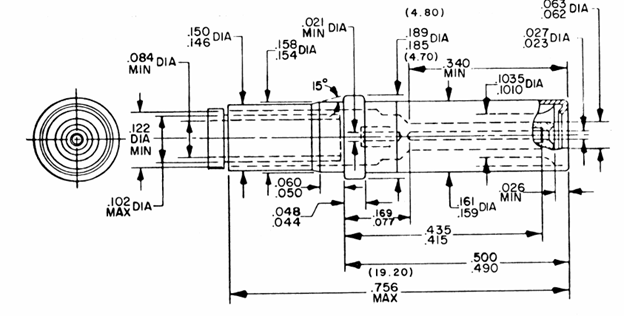
To ensure electrical contact, proper positioning in connector inserts, and cavity size for the terminated wire, the dimensional requirements of contacts are tightly controlled. Source MIL-C-39029/51A
High tensile strength in the contact material is essential as it allows the female socket tines to deflect and rebound with each insertion, ensuring a consistent pressure on the pin for the next mating cycle. This resilience prevents loss of normal force over time, which is crucial for vibration resistance. If a socket’s spring force degrades, vibration can cause momentary contact openings (and signal interruptions), so the material and geometry are chosen to avoid that occurrence. Specifically, MIL-DTL-38999 requires detection of “…discontinuities in excess of 1 microsecond.” While that does not seem like a significant impact, signal applications running at 100MHz would lose 100 bits with a 1 microsecond discontinuity.
Conclusion
The intermateability of electrical contacts is critical for electrical system reliability and performance. Of the many critical factors, the contact retention mechanism, whether front or rear release, must be able to withstand normal operating conditions/stresses without loss of electrical continuity and/or mechanical performance.
There is a great deal more to discuss on contacts, and future Lectromec articles will further discuss the performance requirements, test methods, and selection of electrical contacts.
Contact Lectromec to find out more about our ISO17025:2017 accredited test lab and capabilities to test your electrical wiring interconnection system components.

Michael Traskos
President, Lectromec
michael.traskos@lectromec.comMichael has been involved in the field of EWIS for more than two decades and has worked on a wide range of projects from basic component testing, aircraft certification, and remaining service life assessments. Michael is an FAA DER with a delegated authority covering EWIS certification, the former chairman of the SAE AE-8A EWIS installation committee, and current vice chairman of the SAE AE-8D Wire and Cable standards committee.