View Latest Blog Entries
Close
Categories
Testing & Assessment Certification Standard & Regulation Aging Wires & Systems Maintenance & Sustainment Management Conference & Report Protection & Prevention Research Miscellaneous Arcing
Popular Tags
Visual Inspection High Voltage AS50881 MIL-HDBK MIL-HDBK-525 FAR AS4373 Maintenance Electromagnetic Interference (EMI) FAR 25.1707 Wire System Arcing Damage
All Tags in Alphabetical Order
2021 25.1701 25.1703 abrasion AC 33.4-3 AC 43 Accelerated Aging accessibility ADMT Aging Systems AIR6808 AIR7502 Aircraft Power System aircraft safety Aircraft Service Life Extension Program (SLEP) altitude arc damage Arc Damage Modeling Tool Arc Fault (AF) Arc Fault Circuit Breaker (AFCB) Arc Track Resistance Arcing Arcing Damage AS22759 AS22759/87 AS23053 AS29606 AS4373 AS4373 Method 704 AS50881 AS5692 AS6019 AS6324 AS81824 AS83519 AS85049 AS85485 AS85485 Wire Standard ASTM B355 ASTM B470 ASTM D150 ASTM D2671 ASTM D8355 ASTM D876 ASTM F2639 ASTM F2696 ASTM F2799 ASTM F3230 ASTM F3309 ATSRAC Attenuation Automated Wire Testing System (AWTS) Automotive Avionics backshell batteries bend radius Bent Pin Analysis Best of Lectromec Best Practice bonding Cable Cable Bend cable testing Carbon Nanotube (CNT) Certification cfr 25.1717 Chafing Chemical Testing Circuit Breaker circuit design Circuit Protection cleaning clearance Coaxial cable cold bend collision comparative analysis Compliance Component Selection Condition Based Maintenance Conductor Conductor Testing conductors conduit Connector Connector rating connector selection connector testing connectors contacts Corona Corrosion Corrosion Preventing Compound (CPC) corrosion prevention Cracking creepage D-sub data analysis data cables degradat Degradation Delamination Derating design safety development diagnostic Dielectric breakdown dielectric constant Dimensional Life disinfectant Distributed Power System DO-160 dry arc dynamic cut through E-CFR electric aircraft Electrical Aircraft Electrical Component Electrical Power Electrical Testing Electrified Vehicles Electromagnetic Interference (EMI) Electromagnetic Vulnerability (EMV) Electrostatic Discharge EMC EMF EN2235 EN3197 EN3475 EN6059 End of Service Life End of Year Energy Storage engines Environmental Environmental Cycling environmental stress ethernet eVTOL EWIS certification EWIS Component EWIS Design EWIS Failure EWIS sustainment EWIS Thermal Management EZAP FAA FAA AC 25.27 FAA AC 25.981-1C FAA Meeting failure conditions Failure Database Failure Modes and Effects Analysis (FMEA) FAQs FAR FAR 25.1703 FAR 25.1707 FAR 25.1709 Fault fault tree Fixturing Flammability fleet reliability Flex Testing fluid exposure Fluid Immersion Forced Hydrolysis fuel system fuel tank ignition Functional Hazard Assessment functional testing Fundamental Articles Fuse Future Tech galvanic corrosion Glycol Gold Gold plating Green Taxiing Grounding hand sanitizer handbook Harness Design harness protection hazard Hazard Analysis health monitoring heat shrink heat shrink tubing high current high Frequency high speed data cable High Voltage High Voltage Degradation HIRF History Hot Stamping Humidity Variation HV connector HV system ICAs IEC 60851 IEC60172 IEEE immersion insertion loss Inspection installation installation safety Instructions for Continued Airworthiness insulating material insulating tape Insulation insulation breakdown insulation resistance insulation testing interchangeability IPC-D-620 ISO 17025 Certified Lab ISO 9000 J1673 Kapton Laser Marking life limit life limited parts Life prediction life projection Lightning lightning protection liquid nitrogen lithium battery lunar Magnet wire maintainability Maintenance Maintenance costs Mandrel mean free path measurement mechanical stress Mechanical Testing MECSIP MIL-C-38999 MIL-C-85485 MIL-DTL-17 MIL-DTL-23053E MIL-DTL-3885G MIL-DTL-38999 MIL-E-25499 MIL-HDBK MIL-HDBK-1646 MIL-HDBK-217 MIL-HDBK-454 MIL-HDBK-516 MIL-HDBK-522 MIL-HDBK-525 MIL-HDBK-683 MIL-STD-1353 MIL-STD-1560 MIL-STD-1798 MIL-STD-464 MIL-T-7928 MIL-T-7928/5 MIL-T-81490 MIL-W-22759/87 MIL-W-5088 MIL–STD–5088 Military 5088 modeling moon MS3320 NASA NEMA27500 Nickel nickel plating No Fault Found OEM off gassing Outgassing Over current Overheating of Wire Harness Parallel Arcing part selection Partial Discharge partial discharge at altitude Performance physical hazard assessment Physical Testing polyamide polyimdie Polyimide-PTFE Power over Ethernet power system Power systems predictive maintenance Presentation Preventative Maintenance Program Probability of Failure Product Quality PTFE pull through Radiation Red Plague Corrosion Reduction of Hazardous Substances (RoHS) regulations relays Reliability Research Resistance Revision C Rewiring Project Risk Assessment S&T Meeting SAE SAE Committee Sanitizing Fluids Secondary Harness Protection separation Separation Requirements Series Arcing Service Life Extension Severe Wind and Moisture-Prone (SWAMP) Severity of Failure shelf life Shield Shielding Shrinkage signal signal cable Silver silver plated wire silver-plating skin depth skin effect Small aircraft smoke Solid State Circuit Breaker Space Certified Wires Splice standards Storage stored energy superconductor supportability Sustainment System Voltage Temperature Rating Temperature Variation Test methods Test Pricing Testing testing standard Thermal Circuit Breaker Thermal Endurance Thermal Index Thermal Runaway Thermal Shock Thermal Testing tin Tin plated conductors tin plating tin solder tin whiskering tin whiskers top 5 Transient Troubleshooting TWA800 UAVs UL94 USAF validation verification video Visual Inspection voltage voltage differential Voltage Tolerance volume resistivity vw-1 wet arc white paper whitelisting Winding wire Wire Ampacity Wire Bend Wire Certification Wire Comparison wire damage wire failure wire performance wire properties Wire System wire testing Wire Verification wiring components work unit code
Key Takeaways
  • AC25.981-1C provides guidance on fuel tank ignition mitigation.
  • As little as 200 microjoules can cause fuel vapor ignition.
  • There are tool and techniques that can help with achieving certification.
  • Listen to the podcast here.

The certification of an aircraft requires the expertise of dozens of disciplines coming together for a single effort. Certainly, as the electrical wiring interconnect system (EWIS) has developed over the last couple of decades, the interaction with other systems and components is becoming better understood as the requirements are becoming more pronounced.

One area of aircraft certification where electrical energy and risk have always been considered is the fuel system. While it is obvious that limiting the exposure of fuel to electrical energy is advantageous, how this gets addressed from a safety and certification perspective is far from obvious.

This two-part series covers elements of the EWIS and fuel system, how to gather the necessary data to show compliance, and achieve certification of an aircraft’s fuel system.

Framework

As a starting point, the requirements of 25.981 outline items that must be shown as part of the certification package. Specifically, the first paragraph of 25.981 states “No ignition source may be present at each point in the fuel tank or fuel tank system where catastrophic failure could occur due to ignition of fuel or vapors.” The regulation goes on to identify several specific elements that require electrical and thermal ignition sources around the fuel system to be identified and quantified.

Fuel Ignition Sources
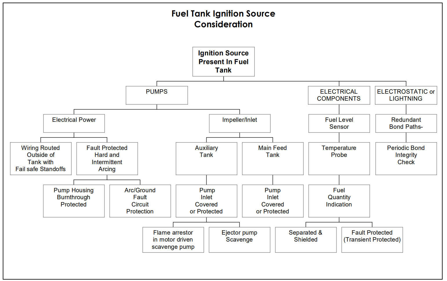
Though not an exhaustive list, this is a starting point area for review of fuel tank ignition sources. Source AC 25.981-1C.

Electrical Threshold

The electrical system cannot inject more than 200 microjoules of energy into the system. As identified in AC 25.981-1C:

“Laboratory testing has shown that the minimum ignition energy in an electrical spark required to ignite hydrocarbon fuel vapor is 200 microjoules. Therefore, for electrical or electronic systems that introduce electrical energy into fuel tanks, such as fuel quantity indicating systems, any electrical arcs or sparks that are created into any fuel tank should be less than 200 microjoules during either normal operation or operation with failures.”

To put this into perspective, a 10A current limited 28VDC arcing event can achieve this energy threshold in less than 1 microsecond. This is an extremely low threshold of energy to achieve, but it is necessary to ensure a safe aircraft.

Thermal Issues

The issues with the thermal energy are much more difficult to assess. According to the regulatory guidance in AC 25.981-1C:

Maximum Allowable Surface Temperatures. A surface temperature within the fuel tank (the tank walls, baffles, or any components) that provides a safe margin under all normal or failure conditions, which is at least 50 °F (10 °C) below the lowest expected auto-ignition temperature of the approved fuels. The auto-ignition temperature of fuels will vary because of a variety of factors (ambient pressure, dwell time, fuel type, etc.). The value accepted by the FAA without further substantiation for kerosene fuels, such as Jet A, under static sea level conditions, is 450 °F (232.2 °C). This results in a maximum allowable surface temperature of 400 °F (204.4 °C) for an affected component surface.”

How to determine the possible surface temperature rise comes down to determining if the condition is safe (as outlined in the second excerpt from AC 25.981-1C).

Contemplate the following example: a wire harness is routed near a fuel tank and it is necessary to determine if there is adequate separation. Here we start with assuming best practices and the wiring is routed above the fuel tank (this is done to prevent fuel tank leakage from interfering with the wiring system). The wire harness is properly clamped and has a 0.5inch separation distance from the fuel tank. Lastly, the wiring harness consists of 115 VAC three phase power wires for electrical equipment that requires a 15-amp circuit protection device. What happens when an electrical arcing event occurs in this scenario?

Next Article

With the electrical and thermal elements of fuel tank ignition prevention defined, the next article will examine the means of gathering the data from both a physical testing and modeling/simulation perspectives.

Can’t wait for the next article? Get a preview of some of the techniques to be discussed #1 and #2.

Michael Traskos

Michael Traskos

President, Lectromec

Michael has been involved in wire degradation and failure assessments for more than a decade. He has worked on dozens of projects assessing the reliability and qualification of EWIS components. Michael is an FAA DER with a delegated authority covering EWIS certification and the chairman of the SAE AE-8A EWIS installation committee.