Key Takeaways
- HIRF control in next-generation aircraft starts with understanding the actual installation of the EWIS components.
- Several sections in Part 25, subpart H, address the relationship between electromagnetic stress and a safely functional EWIS.
- HIRF becomes a particular concern for systems utilizing PWM in which the external RF environment and the internally generated switching environment can interact through the same installed EWIS pathways.
High-Intensity Radiated Fields (HIRF) have often been viewed and treated mainly as an avionics certification problem. For modern aircraft, especially those moving toward higher-voltage power distribution and power-electronic control, HIRF is evolving into an EWIS issue as well. The reason is straightforward: EWIS is the installed pathway through which electromagnetic energy can couple, propagate, and interact with equipment, structure, and other wiring systems. When the electrical architecture includes high-voltage buses and high-frequency switching, the wiring system becomes even more central to whether the aircraft remains robust in the HIRF environment. In this article, we consider the implications and how they might be addressed.
HIRF Rules
The FAA’s primary transport-category HIRF rule is 14 CFR § 25.1317. The regulation requires each electrical and electronic system performing critical or significant functions to be designed and installed so it is not adversely affected by the applicable HIRF environment or equipment test level, depending on the function’s failure condition. The detailed external HIRF environments and equipment test levels used for compliance are defined in Part 25 Appendix L. For the most critical functions, the regulation is tied to continued safe flight and landing; for lower but still important functions, the regulation points to equipment-level HIRF test levels.
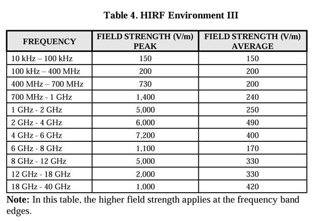
The HIRF requirements depend on the environment conditions. Table 4 from AC 20-158 is the most severe tests conditions identified in the AC. Source: FAA 20-158B
The regulatory wording matters because § 25.1317 is not just about equipment performance in isolation; it is about equipment as designed and installed. The FAA’s current certification guidance, AC 20-158B, reinforces that point. The AC describes HIRF compliance in terms of system safety assessment, installed-system behavior, and installation features such as cable routing, shielding, grounding, bonding, connectors, and termination practices.
EIWS Regulations
That is where EWIS regulations come into the picture. Part 25 Subpart H establishes the FAA certification requirements for EWIS, including sections on system separation, system safety, bonding, protection, and Instructions for Continued Airworthiness. In particular, § 25.1707 addresses system separation, § 25.1709 addresses EWIS system safety, § 25.1715 covers electrical bonding and protection against static electricity, and § 25.1729 requires EWIS Instructions for Continued Airworthiness. None of those sections specifically identifies “HIRF”, but all influence whether a wiring installation can withstand electromagnetic stress without causing unsafe behavior. The closest may be the callout in §25.1707 (b):
“Each EWIS must be designed and installed so that any electrical interference likely to be present in the airplane will not result in hazardous effects upon the airplane or its systems.”
That relationship between HIRF and EWIS is easy to underestimate. External RF fields can couple into aircraft structure, apertures, cable shields, pigtails, wire bundles, and connector interfaces. Once coupled, the disturbance can travel into systems as common-mode or differential stress. AC 20-158B recognizes this by emphasizing aircraft attenuation, transfer characteristics, installed-system evaluation, and the need to consider how real aircraft installation details affect susceptibility.
For conventional low-voltage aircraft systems, HIRF concerns often center on transient errors, false indications, or communication disruption. As bus voltages increase, electrical stress margins at connectors, terminations, and insulation interfaces can shrink, especially in compact installations or low-pressure operating environments. Under those conditions, a HIRF-induced disturbance superimposed on normal operating voltages may not merely produce a logic upset, but it can increase local field stress, aggravate weak shield terminations, or expose marginal insulation interfaces.
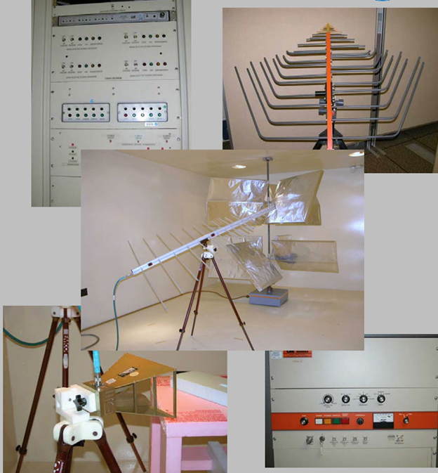
HIRF testing focuses on equipment performance under high energy conditions. If not properly designed, HV EWIS may become a HIRF emitter in PWM applications. Photo Source: NASA.
This becomes even more important when the aircraft uses high-frequency switching, such as PWM (Pulse Width Modulation)-based inverters, converters, and motor drives. PWM systems create steep voltage edges and broad spectral content even when the fundamental switching frequency is not extremely high. Those fast edges can drive common-mode currents through cable capacitances, structure return paths, and shields. The rise time (dV/dt) can also make wiring systems much more sensitive to discontinuities in bonding or shielding. When external HIRF exposure is added on top of that internal electromagnetic environment, the risks are no longer independent. The external RF environment and the internally generated switching environment can interact through the same installed EWIS pathways.
One of the first practical implications is shield termination quality; shielding a cable is meaningless without proper termination. Pigtails, incomplete 360-degree terminations, poor backshell bonding, degraded conductive finishes, or inconsistent ground references can all erode shield effectiveness. AC 20-158B specifically treats shielding, bonding, grounding, and shield terminations as certification-relevant installation features. For HV PWM circuits, that means a shield design intended only for emissions control may not be adequate for HIRF robustness.
System Separation and EWIS Regulations
A second implication is routing and separation discipline. Under § 25.1707, EWIS separation is required so that a failure in one system does not create a hazardous condition in another. In practice, that supports a strong architectural case for deliberate segregation of HV feeders, PWM motor leads, control wiring, low-level sensing circuits, and communications lines. HIRF susceptibility often increases when dissimilar circuits share bundle space or run in parallel without enough consideration of shielding and return-path behavior. In an aircraft with electrically aggressive power electronics, bundle composition and route geometry can meaningfully affect both emissions and immunity.
A third implication is bonding integrity. Under § 25.1715, bonding must support safe current return and protection against hazardous effects. From a HIRF perspective, bonding is also fundamental to electromagnetic control. Poor structural bonds, corrosion at interfaces, degraded jumpers, loose backshell attachment, or non-conductive installation changes can alter return paths and increase susceptibility. For higher-voltage systems, those same deficiencies may also increase local heating or concentrate unwanted electrical stress. This is one reason HIRF should not be treated as only a certification-lab issue; it has a direct continued-airworthiness dimension.
Regulation § 25.1729 requires FAA-approved EWIS Instructions for Continued Airworthiness (ICAs), and the FAA’s EWIS framework is intended to preserve the safety assumptions made during certification. If a design’s HIRF robustness depends on shield continuity, bonding surfaces, special terminations, inspection of clamp locations, or defined repair practices, those features belong in the EWIS ICA and associated maintenance logic. Otherwise, the aircraft may gradually drift away from the certified electromagnetic configuration even though every individual maintenance action seems minor.
From a system-safety standpoint, operating mode matters too. AC 20-158B emphasizes relating HIRF certification to the function performed and the failure condition classification. For HV propulsion, actuation, or power-conversion systems, susceptibility may vary with bus voltage, load state, switching activity, and control mode. A disturbance that is tolerable during one flight phase may become hazardous during another. That is why HIRF evaluation for PWM-driven systems should include representative operating states, not just a nominal bench condition.
Conclusion
For EWIS engineers, the practical takeaway is that HIRF control in next-generation aircraft starts with understanding the actual installation of the EWIS components. It means evaluating cable construction, shield architecture, grounding philosophy, connector selection, backshell design, route separation, and maintenance assumptions together rather than as isolated decisions. It also means recognizing that high voltage and high-frequency switching do not merely add new power capabilities; they change the electromagnetic behavior of the installed wiring system itself and make it not just a victim of HIRF, but also potentially an emitter. This suggests that an update to 25.1705 should be done to cross reference to the HIRF regulations of 25.1317.
HIRF is still an avionics certification topic, but in aircraft with HV distribution and PWM-based power electronics, it is equally an EWIS design topic. The FAA regulations already provide the framework through § 25.1317, Appendix L, and Part 25 Subpart H. The real engineering challenge is wiring system design that ensures the shielding, bonding, routing, and continued-airworthiness controls are strong enough to support the aircraft needs. Done well, EWIS helps to mitigate the HIRF risk; when poorly executed, it becomes the pathway through which the HIRF problem can enter the aircraft. For those interested in evaluating their EWIS risks, contact Lectromec.

Michael Traskos
President, Lectromec
michael.traskos@lectromec.comMichael has been involved in the field of EWIS for more than two decades and has worked on a wide range of projects from basic component testing, aircraft certification, and remaining service life assessments. Michael is an FAA DER with a delegated authority covering EWIS certification, the former chairman of the SAE AE-8A EWIS installation committee, and current vice chairman of the SAE AE-8D Wire and Cable standards committee.