View Latest Blog Entries
Close
Categories
Testing & Assessment Certification Standard & Regulation Aging Wires & Systems Maintenance & Sustainment Management Conference & Report Protection & Prevention Research Miscellaneous Arcing
Popular Tags
Visual Inspection High Voltage AS50881 MIL-HDBK MIL-HDBK-525 FAR AS4373 Electromagnetic Interference (EMI) Maintenance FAR 25.1707 Wire System Arcing Damage
All Tags in Alphabetical Order
2021 25.1701 25.1703 abrasion AC 33.4-3 AC 43 Accelerated Aging ADMT Aging Systems AIR6808 AIR7502 Aircraft Power System aircraft safety Aircraft Service Life Extension Program (SLEP) altitude arc damage Arc Damage Modeling Tool Arc Fault (AF) Arc Fault Circuit Breaker (AFCB) Arc Track Resistance Arcing Arcing Damage AS22759 AS22759/87 AS23053 AS29606 AS4373 AS4373 Method 704 AS50881 AS5692 AS6019 AS6324 AS81824 AS83519 AS85049 AS85485 AS85485 Wire Standard ASTM B355 ASTM B470 ASTM D150 ASTM D2671 ASTM D8355 ASTM D876 ASTM F2639 ASTM F2696 ASTM F2799 ASTM F3230 ASTM F3309 ATSRAC Attenuation Automated Wire Testing System (AWTS) Automotive Avionics backshell batteries bend radius Bent Pin Analysis Best of Lectromec Best Practice bonding Cable Cable Bend cable testing Carbon Nanotube (CNT) Certification cfr 25.1717 Chafing Chemical Testing Circuit Breaker circuit design Circuit Protection cleaning clearance Coaxial cable cold bend collision comparative analysis Compliance Component Selection Condition Based Maintenance Conductor Conductor Testing conductors conduit Connector Connector rating connector selection connector testing connectors contacts Corona Corrosion Corrosion Preventing Compound (CPC) corrosion prevention Cracking creepage D-sub data analysis data cables degradat Degradation Delamination Derating design safety development diagnostic Dielectric breakdown dielectric constant Dimensional Life disinfectant Distributed Power System DO-160 dry arc dynamic cut through E-CFR electric aircraft Electrical Aircraft Electrical Component Electrical Power Electrical Testing Electrified Vehicles Electromagnetic Interference (EMI) Electromagnetic Vulnerability (EMV) Electrostatic Discharge EMC EMF EN2235 EN3197 EN3475 EN6059 End of Service Life End of Year Energy Storage engines Environmental Environmental Cycling environmental stress ethernet eVTOL EWIS certification EWIS Component EWIS Design EWIS Failure EWIS sustainment EWIS Thermal Management EZAP FAA FAA AC 25.27 FAA AC 25.981-1C FAA Meeting failure conditions Failure Database Failure Modes and Effects Analysis (FMEA) FAQs FAR FAR 25.1703 FAR 25.1707 FAR 25.1709 Fault fault tree Fixturing Flammability fleet reliability Flex Testing fluid exposure Fluid Immersion Forced Hydrolysis fuel system fuel tank ignition Functional Hazard Assessment functional testing Fundamental Articles Fuse Future Tech galvanic corrosion Glycol Gold Gold plating Green Taxiing Grounding hand sanitizer handbook Harness Design harness protection hazard Hazard Analysis health monitoring heat shrink heat shrink tubing high current high Frequency high speed data cable High Voltage High Voltage Degradation HIRF History Hot Stamping Humidity Variation HV connector HV system ICAs IEC 60851 IEC60172 IEEE immersion insertion loss Inspection installation installation safety Instructions for Continued Airworthiness insulating material insulating tape Insulation insulation breakdown insulation resistance insulation testing interchangeability IPC-D-620 ISO 17025 Certified Lab ISO 9000 J1673 Kapton Laser Marking life limit life limited parts Life prediction life projection Lightning lightning protection liquid nitrogen lithium battery lunar Magnet wire maintainability Maintenance Maintenance costs Mandrel mean free path measurement mechanical stress Mechanical Testing MECSIP MIL-C-38999 MIL-C-85485 MIL-DTL-17 MIL-DTL-23053E MIL-DTL-3885G MIL-DTL-38999 MIL-E-25499 MIL-HDBK MIL-HDBK-1646 MIL-HDBK-217 MIL-HDBK-454 MIL-HDBK-516 MIL-HDBK-522 MIL-HDBK-525 MIL-HDBK-683 MIL-STD-1353 MIL-STD-1560 MIL-STD-1798 MIL-STD-464 MIL-T-7928 MIL-T-7928/5 MIL-T-81490 MIL-W-22759/87 MIL-W-5088 MIL–STD–5088 Military 5088 modeling moon MS3320 NASA NEMA27500 Nickel nickel plating No Fault Found OEM off gassing Outgassing Over current Overheating of Wire Harness Parallel Arcing part selection Partial Discharge partial discharge at altitude Performance physical hazard assessment Physical Testing polyamide polyimdie Polyimide-PTFE Power over Ethernet power system Power systems predictive maintenance Presentation Preventative Maintenance Program Probability of Failure Product Quality PTFE pull through Radiation Red Plague Corrosion Reduction of Hazardous Substances (RoHS) regulations relays Reliability Research Resistance Revision C Rewiring Project Risk Assessment S&T Meeting SAE SAE Committee Sanitizing Fluids Secondary Harness Protection separation Separation Requirements Series Arcing Service Life Extension Severe Wind and Moisture-Prone (SWAMP) Severity of Failure shelf life Shield Shielding Shrinkage signal signal cable Silver silver plated wire silver-plating skin depth skin effect Small aircraft smoke Solid State Circuit Breaker Space Certified Wires Splice standards Storage stored energy superconductor supportability Sustainment System Voltage Temperature Rating Temperature Variation Test methods Test Pricing Testing testing standard Thermal Circuit Breaker Thermal Endurance Thermal Index Thermal Runaway Thermal Shock Thermal Testing tin Tin plated conductors tin plating tin solder tin whiskering tin whiskers top 5 Transient Troubleshooting TWA800 UAVs UL94 USAF validation verification video Visual Inspection voltage voltage differential Voltage Tolerance volume resistivity vw-1 wet arc white paper whitelisting Winding wire Wire Ampacity Wire Bend Wire Certification Wire Comparison wire damage wire failure wire performance wire properties Wire System wire testing Wire Verification wiring components work unit code

When should you consider adopting an aircraft wire life extension program? Part III

Aging Wires & Systems Maintenance & Sustainment

This is the third article in a series addressing the concepts associated with wire life extension and an Electrical Wire Interconnection System (EWIS) analysis of aging aircraft. The When should you consider adopting an aircraft wire life extension program? article addressed some of the fundamental concepts behind risk and risk assessment and how they are applied to an EWIS investigation. This article focuses on the assessment of failure probabilities for aging aircraft.

Like all devices, a wire is subject to the three standard portions of a device life cycle which include: infant mortality, random failure, and wear-out (more about this process can be found in the Wire Failure and Wire Component Lifecycle article). Infant mortality of devices is associated with manufacturing or installation flaws in the wires; these are detected early and are replaced. The majority of a device’s life is in the random failure portion. Here, device failure is associated with random occurrences such as damage during maintenance actions. The final portion of the device life cycle is the wear-out: parts begin to have reduced performance and eventually stop working as designed.

To determine where the wire is in the life-cycle, the natural first step is to do a physically examination of the wiring system. Visual examinations are able to identify the more obvious damage such as chaffing, pinched wires in clamps, and exposure to possible corrosive fluids. While these are important to identify and resolve, wire insulation degradation is not always visible. Micro-cracks in the insulation or heat damage caused by electrical overloads are difficult to see in an individual wire, much less in an entire bundle of wires.

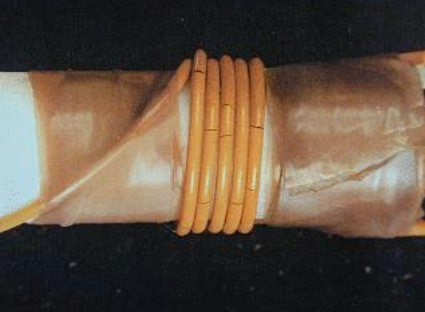
Below is an example of cracks in the topcoat of the wire insulation. These are easy to see when the wire is wrapped around a mandrel, but incredibly difficult to find if straight and in the middle of a wire bundle.

wire life extension
The cracks are down to the conductor

During the Intrusive Inspections performed by the FAA in 2000, a trained team visually inspected wire bundles with the goal of reporting breaches or damage to wires. For one bundle that underwent a thorough visual examination, two wire breaches were found. The same bundle was then selected for additional testing (DelTest™) to be performed by Lectromec. Lectromec’s testing found 60 insulation breaches that exposed the wire conductor (all insulation breaches were independently verified). Thus, visual examinations alone are not sufficient to determine the wires’ condition.

To further complicate the work of visual examination, there are wide differences in the insulation chemical compositions. Different insulation types have different failure modes which present under different chemical, mechanical, or thermal stresses. Each wire insulation type has its strengths and weaknesses. Some do well under one set of type of stress (e.g. fluid emersion) while fail under other types of stress (e.g. repeated mechanical strain).

Regardless of the type of insulation, as the wire ages, it becomes more susceptible to failure. Cracks and tears are more easily formed during maintenance actions and the insulation is more easily worn down from chaffing or being pinched at a clamp. Overtime, cracks in multiple wires will occur in close proximity to one another allowing for crosstalk or power conduction.

Identifying Wire Condition

To determine the health of the wiring itself, it becomes necessary for accelerated aging testing and/or chemical degradation analysis. The specific process for determining the health of the wire is dependent on the objective and the material type. Some of the tests that may be performed include WIDAS, Inherent Viscosity, or Wirelytics (coming soon from Lectromec). The results of these tests which perform accelerated aging and chemical degradation analysis on the wire insulation are used to determine the remaining life of the wire.

The ‘remaining life of the wire’ is a concept that describes where the wire is in the device life cycle. This is not to say that the remaining life is the time at which all wires will fail (a failure defined as a breach that exposes the conductor); rather, this sets an expected threshold at which the degradation related failures would begin.

wire life extension

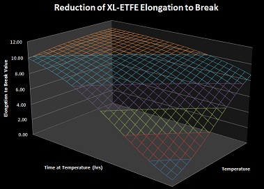
For most wire types, insulation degradation is not a simple linear process. As identified earlier, a number of factors affect the degradation process. To determine the degradation evolution of wire insulation, a great deal of research is necessary to identify the reliable life limit (the point at which the failure probability is expected to increase). The figure on the right shows an example of some of the research Lectromec has performed on XL-ETFE insulated wires.

Lectromec has performed this research on most modern aircraft wire types and continues to perform additional testing to better improve these proprietary analysis techniques. It is this research that Lectromec relies upon for assessing the current wire conditions and projecting the remaining life of the wire.

Michael Traskos

Michael Traskos

President, Lectromec

Michael has been involved in wire degradation and failure assessments for more than a decade. He has worked on dozens of projects assessing the reliability and qualification of EWIS components.