
Wiring Diagram Guidance for Aerospace Systems - MIL-HDBK-863
Introduction
Aircraft wiring schematics require clear standardized diagrams for design, fabrication, installation, maintenance, and safety assessments. This is not unique to aerospace, but there are common practices that the aerospace industry uses to ease the transition from platform to platform. A useful reference in this domain is MIL-HDBK-863, the DoD Handbook for wiring data and system schematic diagrams. This article explores the scope of MIL-HDBK-863, details it prescribes for wiring schematics, discusses some gaps, and other relevant wiring diagram standards.
Scope
MIL-HDBK-863 is focused on the “preparation and presentation of wiring data and schematic diagrams for aerospace vehicles and their support equipment”. In practice, this means it lays out how to create electrical wiring diagrams that depict an aircraft’s components interconnections (or EWIS) or related systems. The handbook is intended to ensure the diagrams serve multiple important purposes:
- Configuration Control: The wiring documentation can be used to track and control configuration changes in complex electrical systems. Thankfully, software tools now can assist in tracking these changes through multiple revisions.
- Technical Publications: Wiring diagrams in alignment with MIL-HDBK-863 can be directly incorporated into maintenance manuals and technical standards orders (TSOs) without needing redrawing. This saves time and reduces errors when publishing wiring diagram manuals.
- Maintenance Training: Consistent schematics help train aircraft maintainers by presenting circuits in a standardized format that is easier to learn and interpret. Standardized symbols and design patterns reduce (but do not eliminate) the chance of misinterpretation.
- Troubleshooting/Fault Isolation: The MIL-HDBK-863 guidelines support developing source data for fault isolation logic and analysis, meaning the schematics include the information needed for systematic troubleshooting of electrical issues.
Note that MIL-HDBK-863 is a guidance document and that it provides recommended best practices rather than enforceable rules. As such, circuit designers can mold the document as they see fit to meet the needs of their platform.
Expected Details of Aerospace Wiring Schematics
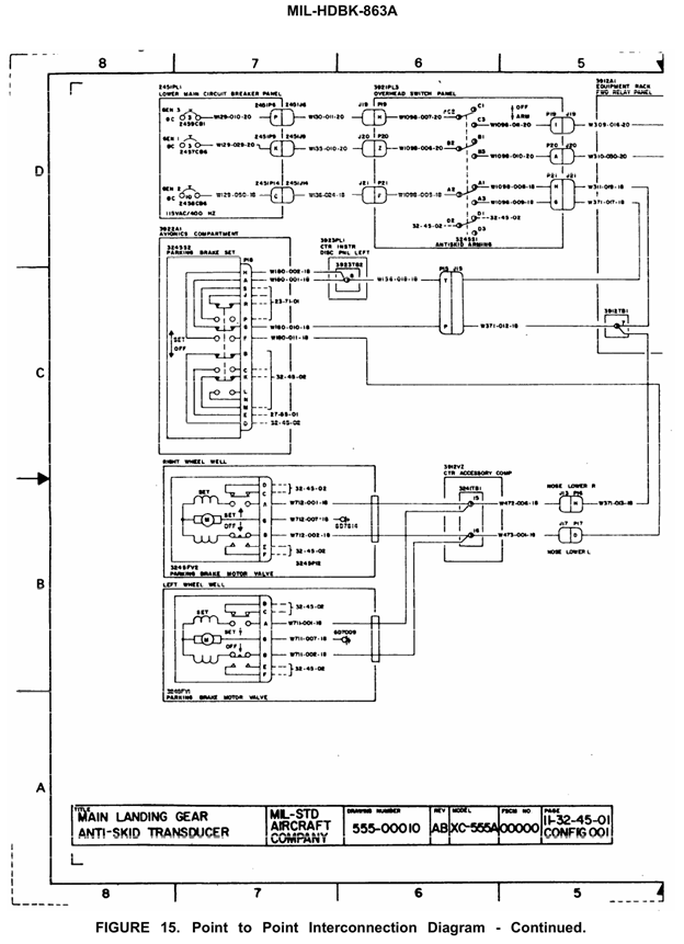
At the core of the wire schematics there should be a lot of detailed information to ensure complete understanding of the electrical system; diagrams with information, callouts, labels, etc., help quickly convey the right information and limit the potentials for misinterpretation. The handbook lays out conventions for symbols, labels, and data so that anyone reading the schematic can identify every component and connection. Here are some of the expected details found in a compliant aerospace wiring diagram:
- Circuit Protection Details: All circuit protection devices such as circuit breakers or fuses should be clearly shown with their relevant ratings. MIL-HDBK-863 specifies that circuit breakers should be identified by their current rating and supplied voltage. For example, a circuit breaker in a 28 VDC aircraft power system might be labeled with its amperage (e.g. 5 A) and noted as a 28 VDC device. This level of detail ensures that anyone using the schematic knows the exact capacity and type of each protective device in the system. Further calculations of the wire ampacity are handled separately.
- Power Distribution and Transformers: Power sources, buses, and transformers are depicted with informative annotations. Transformers should be identified by their input/output voltage and output current rating (or at a minimum, the output voltage must be stated). The idea is that this information helps engineers quickly understand the power conversion taking place at that point in the circuit.
- Complete Wiring Connectivity: All wires, cables, and harnesses are shown connecting to their respective endpoints (equipment, connectors, terminals) in the schematics. The guidance says interconnection diagrams should be prepared to “clearly show all wiring” for the system. Each wire typically carries an identifying code or number, often indicating the circuit and wire gauge, which correlates with wire lists or tables. By following the handbook, the wiring diagram and the accompanying wire list/table together provide a full mapping of the electrical connections. Naturally, the wire identification should align with the OEM circuit markings on the physical wire or cable.
- Connector and Pin Identification: Connectors are usually drawn with pin labels, and those pins are cross-referenced to the wires that attach to them. MIL-HDBK-863, in concert with drawing standards, supports using standardized labeling (like alphanumeric pin codes) for connectors. Further, recommendation on common shield termination practices are lacking, but can be filled in with other specification. The end result is that a technician can look at the diagram and see exactly which pin of a connector a given wire lands on, with nothing ambiguous.
- Component Reference Designations and Ratings: Every component (switches, relays, motors, etc.) on the schematic is represented by a symbol and typically a reference identifier (like “K1” for a relay, “S3” for a switch, etc.), following standards for schematics (which often align with IEEE 315/ANSI Y32 graphical symbols or their modern equivalents). MIL-HDBK-863 leverages such symbol standards rather than redefining them; it references prevailing drawing practices like ASME Y14.100 and line convention standards (ASME Y14.2) to ensure symbols and notations are consistent. Components may also include brief notes on key specs in the diagram – for example, a motor might have its power rating or a lamp its voltage noted if needed for clarity. Lastly, if appropriate, suitable replacement parts may be listed in the notes if the component may be hard to source.
- Parallel Depiction of Redundant Wiring: The handbook even provides guidance on how to draw the wiring lines themselves. For instance, it mentions that for printed presentation, parallel lines should be used on wiring diagrams where appropriate. This is often done to represent cables or bundles with multiple conductors running together, or to neatly show multiple identical phases of a system. The idea is that the diagram remains uncluttered yet complete, adhering to a consistent visual style.
Conclusion
In summary, an MIL-HDBK-863 style schematic is rich with information – from the ratings of circuit breakers and transformers to every wire’s routing and termination. This level of detail is expected so that the diagram can serve as a standalone reference for understanding or troubleshooting the electrical system. A maintainer using such a diagram can locate a faulty wire or component and know its characteristics (like wire size or breaker rating) without flipping through multiple documents. The clarity and completeness reduce guesswork. As an example of the handbook’s thoroughness, if a power panel contains circuit breakers and indicators, the schematic not only shows their connections but also identifies them with the same labels as on the actual panel, and notes their electrical ratings. Such practices make wiring diagrams an effective tool for both engineers and technicians.