
Use of Cables on Aircraft - Part 1
Electrical wire cables are an integral part of an aircraft’s Electrical Wire Interconnection System (EWIS). It would be difficult to imagine the design of an aircraft electrical system without the use of electrical cables. The use of cables in aircraft has simplified the formation of wire harnesses and installation of electrical components (think of the ease of installing one cable versus 15 individual wires on an existing platform).
Since there is such a wide spread of cable applications, the number of options available to designers can be overwhelming (the NEMA27500 standard covers more than 100 million cable configurations). In this article, we will go over the fundamentals of cables, and overview of the constituent components of cables. Part 2 will continue with the cable design overview.
Cable Fundamentals
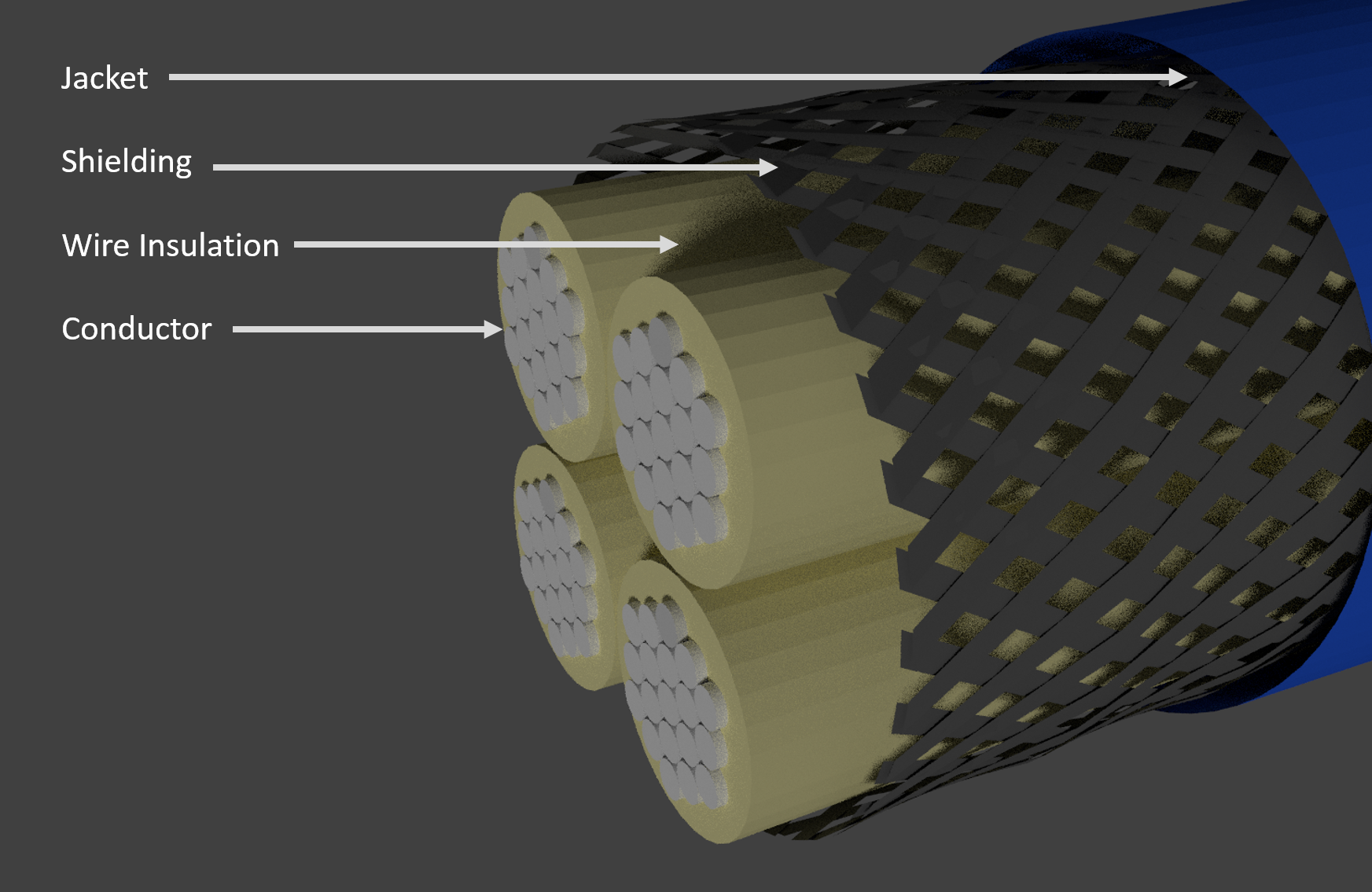
A cable may consist of several components, which at its most basic level is a wire that may include some or none of the following:
- Grouped wires: Whether by twisting together or by grouping via a jacket
- Shielding: A conductive layer outside of the signal/power carrying wires
- Jacket: The outermost insulation layer to protect the cable components
- Cable standards, such as the NEMA 27500 (or MIL-DTL-27500), provide a framework for cable selection. For those unfamiliar with cable identifiers, the part identifiers can be intimidating, but are simple and are broken into seven parts. For this example, we will use the part number M27500 H 20 DC 15 T 24 (note: the spaces have been added for clarity).
|
M27500 |
H |
20 |
DC |
15 |
T |
24 |
|
Specification Part Number |
Cable Identification and Shield Coverage |
Conductor Size |
Wire Specification |
Number of Wires |
Shielding Material |
Jacket Material |
1 - Specification Part Number
The specification is the first part of the identification. For the 27500 style cables, the first six characters are the specification “M27500”. To find out more about the particular specification, this can be grabbed from the ASSIST website – though this is the earlier revision. The most recent version can be purchased from NEMA.
2 - Cable Identification and Shield Coverage
This identifier has two parts to it. The cable identification includes the use of colors to identify wire number and/or the wire size. There are six different component wire configuration identification options – more than enough to match the needs of any application. With the shielding, there are three options: no shielding, 85% coverage, and 90% coverage. Further discussion about shielding can be found in Part 6.
The reason why the cable identification and shield coverage option is combined into a single letter is that, given the current configuration of cable identification, 16 characters are used. For many of the cable suppliers/producers, there is a 16-character limit on the cable marking tools. Thus, to get all of the information into the cable identifiers, the designers had to compress information.
Table source MIL-DTL-27500 Rev H
| Unshielded Cable or Minimum 85% Shield Coverage | |
| “-” | for the preferred identification method using color for basic wires (scheme 1) |
| “F” | for the preferred identification method using color for basic wires (scheme 2) |
| “A” | for optional identification method A, using color for basic wires (scheme 1) |
| “G” | for optional identification method A using color for basic wires (scheme 2) |
| “B” | for optional identification method B using color scheme for basic wire sizes (scheme 3) |
| “K” | for optional identification method C |
| “L” | for optional identification method D |
| When a Minimum Shield Coverage of 90% is Required | |
| “C” | for the preferred identification method using color for basic wires (scheme 1) |
| “H” | for the preferred identification method using color for basic wires (scheme 2) |
| “D” | for optional identification method A, using color for basic wires (scheme 1) |
| “J” | for optional identification method A using color for basic wires (scheme 2) |
| “E” | for optional identification method B using color scheme for basic wire sizes (scheme 3) |
| “M” | for optional identification method C |
| “N” | for optional identification method D |
3 - Conductor Size
For NEMA style cables, the constituent wires of a cable all will be the same conductor gauge and same wire specification. For application purposes, if a system requires multiple wire gauges (e.g. to support multiple voltages and current carrying needs), a single cable will not support this – a harness consisting of wires and/cables will be required for the application.
4 - Wire Specification
Similar to the conductor sizing, the wire specification of the cable component wires is uniform, so only one wire type (specification and sizing) is permitted into a NEMA27500 cable. The wire specifications that are available for these cables include those from the AS22759, AS81044, MIL-DTL-25038, and MIL-DTL-81381 families.
The selection of component wire, just like standalone-wire, is based on the particular application. Factors that are the leading
- Termination Type (i.e. does the conductor need to be solderable?)
- Offgassing Requirements (typically for space applications or sealed systems)
- Temperature Rating: This is true for all parts of the cable assembly and should not be only considered for the component wires. It could be considered wasteful to get component wires rated for 200C with an outside jacket rated to only 100C.
- Fluid Resistance: Although the cable may have an insulating outside jacket to protect from fluid exposure, the wires may come in contact with fluids at or near the connectors. Although the length of wire exposed to the fluid is limited, there could still be potential impacts.
Table source MIL-DTL-27500 Rev H
| ID | Wire Specification | ID | Wire Specification |
| A | MIL-W-5086/1 | NK | MIL-W-81381/21 |
| AA | MIL-W-5086/5 | NL | MIL-W-81381/22 |
| AB | MIL-W-5086/6 | P | MIL-W-5086/4 |
| AD | MIL-W-5086/7 | RA | MIL-W-22759/3 |
| B | MIL-W-5086/2 | RB | MIL-W-22759/4 |
| C | MIL-W-5086/3 | RC | MIL-W-22759/11 |
| CA | MIL-W-22759/13 | RE | MIL-W-22759/12 |
| CB | MIL-W-22759/14 | SA | MIL-W-22759/7 |
| CC | MIL-W-22759/15 | SB | MIL-W-22759/32 |
| E | MIL-W-22759/2 | SC | MIL-W-22759/33 |
| EA | MIL-W-22759/1 | SD | MIL-W-22759/34 |
| F | MIL-W-8777, MS27110 | SE | MIL-W-22759/35 |
| H | MIL-W-8777, MS25471 | SM | MIL-W-22759/41 |
| JA | MIL-W-25038/1 | SN | MIL-W-22759/42 |
| JB | MIL-W-22759/28 | SP | MIL-W-22759/43 |
| JC | MIL-W-22759/29 | SR | MIL-W-22759/44 |
| JD | MIL-W-22759/30 | SS | MIL-W-22759/45 |
| JE | MIL-W-22759/31 | ST | MIL-W-22759/46 |
| JF | MIL-W-25038/3 | TA | MIL-W-22759/8 |
| LE | MIL-W-22759/9 | TE | MIL-W-22759/16 |
| LH | MIL-W-22759/10 | TF | MIL-W-22759/17 |
| MD | MIL-W-81044/5 | TG | MIL-W-22759/18 |
| ME | MIL-W-81044/6 | TH | MIL-W-22759/19 |
| MF | MIL-W-81044/7 | TK | MIL-W-22759/20 |
| MG | MIL-W-81044/8 | TL | MIL-W-22759/21 |
| MH | MIL-W-81044/9 | TM | MIL-W-22759/22 |
| MJ | MIL-W-81044/10 | TN | MIL-W-22759/23 |
| MK | MIL-W-81044/11 | VA | MIL-W-22759/5 |
| ML | MIL-W-81044/12 | WA | MIL-W-22759/6 |
| MM | MIL-W-81044/13 | WB | MIL-W-22759/80 |
| MR | MIL-W-81381/7 | WC | MIL-W-22759/81 |
| MS | MIL-W-81381/8 | WE | MIL-W-22759/82 |
| MT | MIL-W-81381/9 | WF | MIL-W-22759/83 |
| MV | MIL-W-81381/10 | WG | MIL-W-22759/84 |
| MW | MIL-W-81381/11 | WH | MIL-W-22759/85 |
| MY | MIL-W-81381/12 | WJ | MIL-W-22759/86 |
| NA | MIL-W-81381/13 | WK | MIL-W-22759/87 |
| NB | MIL-W-81381/14 | WL | MIL-W-22759/88 |
| NE | MIL-W-81381/17 | WM | MIL-W-22759/89 |
| NF | MIL-W-81381/18 | WN | MIL-W-22759/90 |
| NG | MIL-W-81381/19 | WP | MIL-W-22759/91 |
| NH | MIL-W-81381/20 | WR | MIL-W-22759/92 |
The component wires are typically tested separately and are certified independently.
End of Part 1
The engineering that goes into cable design and manufacturing cannot be understated. The selection of each part of a cable’s configuration for an application impacts not only the original design, but also how the system will be maintained. Because of the long term impact the cable selection may have (for good or bad), it can be beneficial for a comparative analysis for your application. Supported by testing and engineering knowledge, Lectromec can help to ensure the cable selected is the best for your application.
The next article will cover parts 5, 6, and 7 (Number of wires, shielding materials, and jacket materials, respectively).