
The Use of Splices
Splices are a commonly implemented means of joining circuits. They provide an easy and reliable means to join two wires and can be done with minimal tooling. It is important however that the restrictions for the use of splices are followed to ensure a safe and reliable aircraft wiring system; improper use can have a direct impact on system performance and failures that have both physical and functional impacts.
Fundamentals
First and foremost, what is a splice? A splice is a metal ferrule that is crimped to an incoming wire conductor on one side and crimped to an outgoing wire on the other side. While there are numerous varieties of splices that do include configurations allowing for multiple wires to be spliced, such as necessary for data cables, at the core design, the wire splice is about joining two conductors together. This may be done for a variety of reasons such as:
- Replace damaged sections of wire,
- Support the installation of new or modified equipment,
- Extend the length of a wire to facilitate repairs and maintenance, and
- Support production breaks in harnesses fabrication.
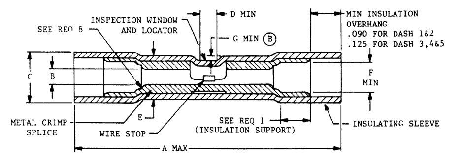
The diagram for a MIL-T-7928/5 splice is shown here. Notable features include:
- Inspection window to identify that the conductors are fully inserted.
- Insulation sleeving that extends beyond the end of the ferrule to protect the conductive members. The sleeving is wider than the metal ferrule making it possible to still have wire insulation under the splice.
- Locator window that typically consists of a transparent or translucent portion in the insulation or housing of the splice, allowing technicians or inspectors to visually confirm that the wires are properly inserted, aligned, and securely connected within the splice enclosure. This feature enhances the efficiency and reliability of wire splicing operations by enabling quick visual checks for quality assurance and troubleshooting without the need for specialized tools or dismantling of the splice.
- A wire stop to prevent an inserted wire from going beyond the midpoint of the splice.

The AS81824 splices, transferred from the MIL-S-81824, are a class of aerospace-grade splices designed to be environmentally sealed; the splice insulation is heat shrink tubing allowing for compression of the insulation around the wire insulation. Furthermore, the AS81824 splices are designed for single wires and coaxial cables, and options exist for both heat sealing of the splice and cold seals for areas that are harder to maintain due to space constraints preventing the use of a heat gun.
Restrictions
When considering the use and installation of splices on aircraft, there are dozens of restrictions to ensure that the splices do not degrade the circuit performance or the mechanical integrity of the wiring. Ideally, splices are to be avoided as each cut, crimp, and termination of a circuit adds the potential for damage. Even with the best environmental seal on a splice, each creates an opportunity for fluid ingress. Furthermore, splices weaken the mechanical strength on the wiring segment. A factor that is often overlooked: smaller gauge wires (smaller than 20AWG) will frequently have the mechanical strength carried by the insulation, not the conductor. This means that, for splices of smaller gauge wires, there is a greater chance that the mechanical strength will be negatively impacted as the insulation is removed and the conductor is used to carry any mechanical stress.

First, it is a good design practice to limit the number of splices in each wire segment between two connectors or termination devices. Ideally, this number should be no greater than one. Again, the rationale for this is that for every splice added to a circuit, the mechanical performance the grades, the flexibility decreases, new failure points are added to the circuit, and potentially additional electrical degradation with increased voltage drop along the circuit. The solder splices are the exception as they are used to connect cable shielding with the connector shell.
Ideally, splices should not be part of primary power distribution and there are a couple of reasons for this. One, primary power distribution carries a lot of power and any additional resistance in the circuit may lead to premature degradation due to heating at the splice point. Second, the primary power distribution is a critical part of an aircraft’s electrical system and as discussed earlier, the addition of splices can reduce the reliability of the circuit.
Clamps
Wherever possible, splices should not be placed under any mechanical clamps. Consider the physical configuration of a wire harness under a clamp; a wire bundle is usually compressed a little bit and deformed due to the clamp grommet pressure onto the wire harness. Where this becomes an issue with splices is that the mechanical stress on the splice may manifest in a couple of ways:
- Push the edges of the splice into other wires within the wire harness; this can result in a stress point on the wire insulation and result in premature damage and degradation of other wires in the wire bundle.
- Cause additional mechanical stress on the spliced wire’s conductor which again should be avoided.
Flex Applications
Not installing splices into sections of wire that are in dynamic flex areas is perhaps the most obvious location-specific prohibition for splices. As splices tend to be more rigid, the installation of one created an unbendable section of the wire. This results in additional mechanical stress on the conductor at the crimp joint, additional stress on the wire at the ends of the splice, and likely results in a premature failure of the wiring in this location. If a wire needs to be repaired in such a location, then there are two options:
- Replace the wire entirely. While this is not ideal from a labor and materials perspective, it is the best option in many cases to ensure long-term reliability.
- Splice the wire outside of the flex area. This does mean that there will be two splices in the wire segment, but this does allow for a section of wire to be repaired and prevents the splice from being installed in the flex area. This option is not recommended as a long-term solution as there is a recommendation from AS50881 to limit the number of splices to no more than 1 per segment.
The Last Word
Splices are a key part of wiring systems as they provide solutions for forking circuits, distribution, connecting production harnesses at logical fabrication locations, and repair/maintenance. As with other parts of the wiring system, the use of splices requires the use of the right part, in the right place, under the right conditions, and installed with the right tools; each one of these factors requires time and attention to detail.