
Life prediction of aircraft EWIS components
Aircraft vehicle reliability rests on well-designed components maintaining full functionality through the entire life cycle, or at the very least, maintaining full functionality until a predictable life limit is reached so that sustainment activities can be performed.
Selection of wires and EWIS components is no different. The selection process starts with the functional requirements (electrical load, functionality, etc.) followed by defining the physical requirements (environmental factors, mechanical stresses, chemical resistance, etc.). Defining the operational environment characteristics should reduce the list of possible wire/cable specifications to a couple of candidates. But what if the list of candidates doesn’t match your need? What should you do if the configuration is outside the known test parameters for a given wire specification?
Limits of Specifications
There is only so much information that can be gathered from wire specifications. The reason for this is most wire specifications set a minimum performance level. As seen in the following figure, although the product from some companies perform significantly better than others, they are grouped together and sold under the same standard.
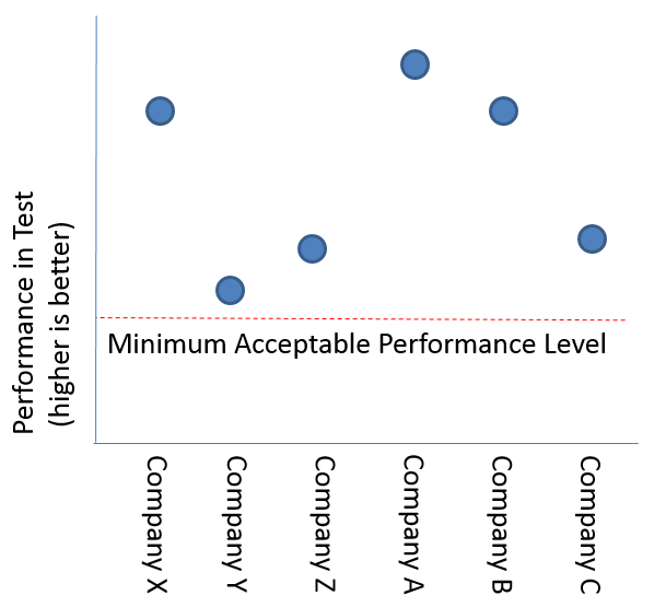
If a wire standard requires passing a 1000 cycle scrape abrasion test, how does that help with defining a life limit in your operational environment? Although it does provide a starting point for comparative analysis, it will unlikely help to define an estimated service life. In some cases, it may be necessary to perform an analysis of the component.
Define the scope
There are more than 60 tests outlined in the AS4373 standard. These cover electrical, mechanical, chemical, quality assessment, and thermal endurance of completed wire constructions. To assess each possible combination of tests would take a large budget and a lot of patience.
In Lectromec’s experience the wire and cable longevity comes down to determining the electrical, physical, and/or functional End Of Life (EOL). The following is a summary of each consideration:
- Electrical EOL #1: Voltage breakdown: this is when the wire insulation can no longer act as a dielectric and electrical voltage is no longer contained to the conductor.
- Electrical EOL #2: Corrosion: this is when the conductor (or shield) has been exposed to some environmental factor that the wire/cable starts to act as a resistor and less like a conductor of electricity.
- Mechanical EOL #1: from repeat flexing of the wire/cable, the strands wear down or break and an open is formed in the circuit.
- Mechanical EOL #2: the insulation is undergoing a stress from pressure or abrasion and eventually is damaged to a point that the conductor is making contact with the stress actor.
- Functional EOL #1: in the case of signal wires/cables, signal corruption may be worse than degradation from other factors outlined above. This may be caused by degradation of the conductor/shield or the dielectric.
The more typical of these is E#1 and M#2. Lectromec recommends not trying to solve all possible combinations of component degradation, but focus on the particular application(s) that are causing the problem(s).
The obvious benefits of this are that the test matrix is dramatically reduced leading to a faster result combined with a lower cost.
Electrical Limits
In a March 2014 blog called High Voltage Testing Considerations, we talked about high voltage testing of wires as they near EOL. The same consideration should be made for the test configurations where EOL determination is necessary.
For those who did not read it, this simply stated, if you have a 28VDC system and an insulation breach is found with a dielectric test performed at 1500VAC, how much cable service life was lost due to the high voltage? For many applications, Lectromec argued that finding a breach in such a way (and potentially creating the breach with the voltage) during a routine EWIS inspection is worth the risk – better to find it on the ground during routine inspections than an in-service failure.
But what if your application is unrecoverable or not easily replaceable? In these cases, determining the voltage end of life condition should use a voltage closer to the expected maximum application voltage. Doing so is likely to provide a better estimate of EOL conditions.
Mechanical Limits
When considering the mechanical stresses, consider the following types of mechanical stresses:
- Is the cable is in a flex environment (e.g. doors or high maintenance areas?
- Is it likely that the cable may rub/sway against structure of other components?
- Is it possible that static force (e.g. resting against a corner, pinching, etc.), may occur?
- How much damage is likely during installation?
In Lab Testing
When testing for EOL, unless the environment is extremely severe, it is recommended that accelerated aging techniques be applied. Waiting for 10k hours to determine if a component will last 10k hours is often not feasible from a project or financial viewpoint, testing is often performed at elevated temperatures. For example, if the objective is to determine component EOL at 200oC, testing performed at 220 or 240oC will expedite the time to failure.
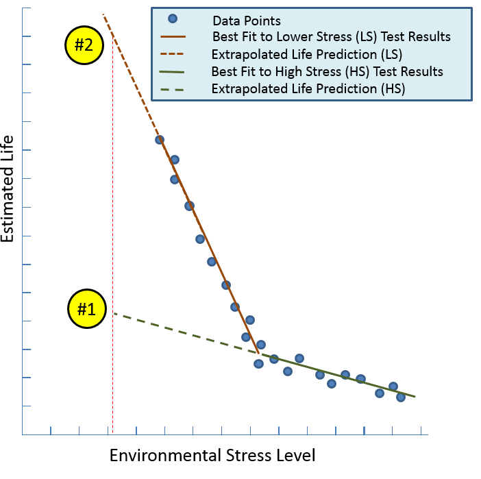
Multiple higher stress configurations are necessary to determine the impact on component life. Care has to be taken to ensure that the conditions used are not so severe that they are beyond the accepted materials limits. In such cases the material may begin to experience degradation mechanisms that are entirely unlikely to happen in an actual service environment.
Once the conditions have been selected, then comes selecting the sample size. In the above figure, a large number of data points were gathered for this configuration with different environmental stress levels. There are two important takeaways from the above figure: 1) If testing were only performed at the highest couple of stress levels, then a much shorter service life would have been predicted (Life prediction #1), and 2) the least severe condition was still above the estimated in-service stress level, but provided a starting point for setting a service life limit on the component (life prediction #2).
In Application
Defining a component service is not as simple as throwing the item into a high stress test setup and gathering the results. Planning and proper consideration is necessary to get valuable, applicable results for your application.