
Heat Shrink Tubing Flammability Tests
Heat shrink tubing is a commonly used component in a wide variety of wiring applications; its applications include electrical insulation (particularly at termination points where conductor may be exposed), abrasion resistance, insulation repair, wire management (bundling), etc.
As is the case with many components in electrical wiring, one of the most important properties of heat shrink tubing is its resistance to fire. Here, we take a look at several methods used to determine and categorize the flame-resistant properties of heat shrink insulation tubing.
VW-1
When simply searching online for a heat shrink tubing product, one is most likely to come across products identified as “VW-1 flame retardant”. The VW (Vertical Wire) test comes from the UL 1581 (Reference Standard for Electrical Wires, Cables, and Flexible Cords) which covers components in operating environments of 90oC – 105oC; one may immediately recognize that the scope of UL 1581 is insufficient for most aerospace applications, however, it is worth briefly discussing here since it is so commonly used.
The VW-1 is a general test that applies to insulation materials in general, not exclusively heat shrink tubing. Performance of the test consists of five cycles of 15-second flame application, between each is a period in which the flame is removed for 15 seconds or until any flame still burning on the specimen extinguishes, up to 60 seconds.
UL94
Another common means of classifying flame resistance is the UL94 (Standard for Safety of Flammability of Plastic Materials for Parts in Devices and Appliances testing) rating system. Similar to the VW-1 test, the UL94 is not explicitly applicable to aerospace, but the results of the testing provide valuable insight for aerospace component selection.
The UL 94 provides means of classifying/ rating the flammability of plastic parts as described in the table below:
| ID | Test Configuration | Criteria |
| HB | Horizontal Burning Test | Burning stops within 100mm or burning rate under 76 mm/ minute for plastics with thickness less than 3mm |
| V-0 | Vertical Burning Test | Flame extinguished within 10 s Non-burning plastic drops permitted |
| V-1 | Vertical Burning Test | Flame extinguished within 30 s; Non-burning plastic drops permitted |
| V-2 | Vertical Burning Test | Flame extinguished within 30s Burning plastic drops permitted |
| 5VB | Vertical burning test – bar and plaque specimens | Flame extinguished within 60s, No drips; burn-through hole permitted |
| 5VA | Vertical burning test – bar and plaque specimens | Flame extinguished within 60s, No drips; Burn-through hole not permitted |
Note that the flame source for the “5V” classifications is much more severe (approx. 5X) than that of the other ratings.
AS23053 Rev A
The AS23053 Rev A (Insulation Sleeving, Electrical, Heat Shrinkable, General Specification for) is an SAE aerospace-specific standard and is the most directly applicable to heat shrinkable tubing for use in aerospace applications. The standard thoroughly details all the qualification testing requirements for heat shrinkable tubing and will be discussed in more detail in a future Lectromec article (Check back for a link at a later date).
Regarding flammability, the AS23053 calls for testing in accordance with ASTM D2671 which, in turn, calls for testing in accordance with ASTM D8355.
ASTM D8355
The ASTM D8355 is titled: Standard Test Methods for Flammability of Electrical Insulating Materials Used for Sleeving or Tubing. The standard covers four test methods for evaluating the flammability resistance of insulating materials, two of which (methods C and D) apply specifically to heat shrink tubing although AS23053 also permits the use of Method A as applicable.
Method A
As described in the standard, Method A “assesses the resistance to spread of flame of the material, by measuring burn length and duration of burning.” This method may be applied to other electrical insulation materials besides heat shrink tubing.
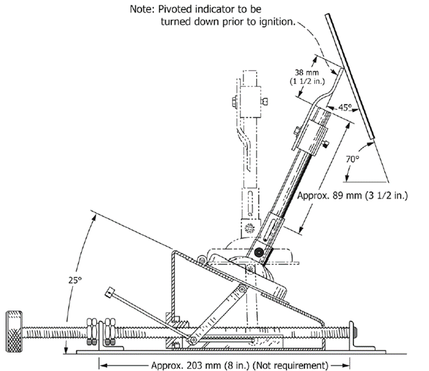
The testing apparatus can be found in the attached image. The test specimen is fixed at 70o with the horizontal; the burner is capable of rotating 25o from the vertical such that the flame is applied at an angle of 45o with the specimen. Testing consists of a single 15-second exposure to flame after which time the flame is removed and the time required for the flame to self-extinguish on the specimen is recorded. This procedure is repeated on a minimum of five specimens of the material under test. For each specimen, the burn length and duration of burning after removal of the applied flame are reported.
Methods C and D
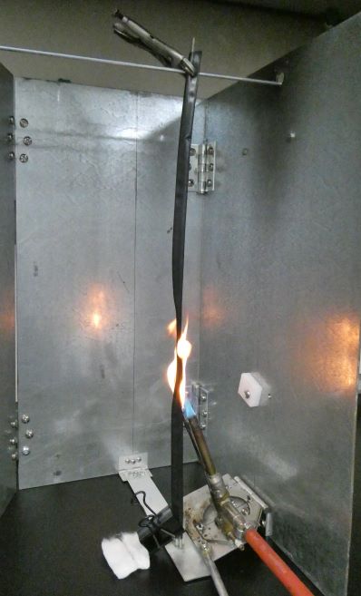
Methods C and D evaluate the tendency of the specimen to propagate flame upward when the test flame is applied at an angle of 70o to the underside of a vertically mounted sample. Method D also evaluates the sample’s ability to spread fire to surrounding flammable materials; to this end, a sheet of medical cotton is placed under the test stand intended to catch any burning drops from the specimen. Any resulting ignition of the cotton demonstrates the sample’s ability to spread the flame.
In each method, the specimen is pre-shrunk around a metal mandrel, this is where the methods begin to differ. Method C calls for a mandrel of diameter equal to that of the identified recovered diameter from the sample’s specification sheet; Method D calls for a thin support wire much narrower than that of the recovered diameter. Because this allows for the potential of a ‘chimney effect’ within the material under test, Method D is considered to be a more severe test.
Performance of methods C and D consist of five cycles of 15-second flame application. In Method C, the flame is removed from the specimen for 15 seconds between each flame application cycle. In Method D the flame is removed from the specimen for 15 seconds or until any flame still burning on the specimen extinguishes, whichever is longer.