
Current Cycling and Aluminum Crimp Terminals
A wire termination can appear mechanically sound and still be developing into an electrical problem. This is particularly important for high-current circuits, where relatively small changes in termination resistance can generate significant heat and voltage drop.
For aluminum conductors, the concern is amplified by the material's electrical and mechanical characteristics. Just like any other termination on an aircraft, termination of aluminum conductors must remain stable even while the conductor repeatedly heats and cools during normal operation. Over time, thermal expansion, contraction, oxidation, and changes within the crimp interface can increase resistance even though the termination remains physically intact.
In this article, we review the current-cycling test contained in SAE AS70991, identify the rationale for the test, provide a general overview of the test itself, and examine some of the failure modes we hope are avoided by selecting components that pass the current-cycling test. Rather than simply determining whether a terminal survives a high-current exposure, the test repeatedly heats and cools the terminated conductor while monitoring whether the crimp remains electrically and thermally stable.
Why Current Cycling Matters
An ideal crimp creates a low-resistance electrical path between the conductor strands and the inner surface of the terminal barrel. The crimping process compresses the conductor strands, reduces internal void space, and ideally establishes an almost continuous area of metal-to-metal contact through which current can transfer from the conductor into the terminal.
Aluminum's propensity to rapidly develop a surface oxide presents an additional challenge in establishing and maintaining this metal-to-metal contact. The aluminum oxide layer is electrically insulating, meaning that a termination cannot rely simply on light surface contact between the barrel and conductor. This is one of the challenges with electrically conductive materials: using a low-precision instrument such as a handheld multimeter to measure resistance may indicate low resistance (0.1 ohms or less), but this value is achievable so long as a single conductor strand is in contact with the barrel.
Ensuring the right tooling is used, together with training on proper termination preparation, is the best way to prevent avoidable degradation due to oxidation in an insufficient crimp. Problems can become more apparent with insufficient crimp pressure, poor crimp positioning, damaged conductors, or any number of other preparation issues as the connection repeatedly heats and cools.
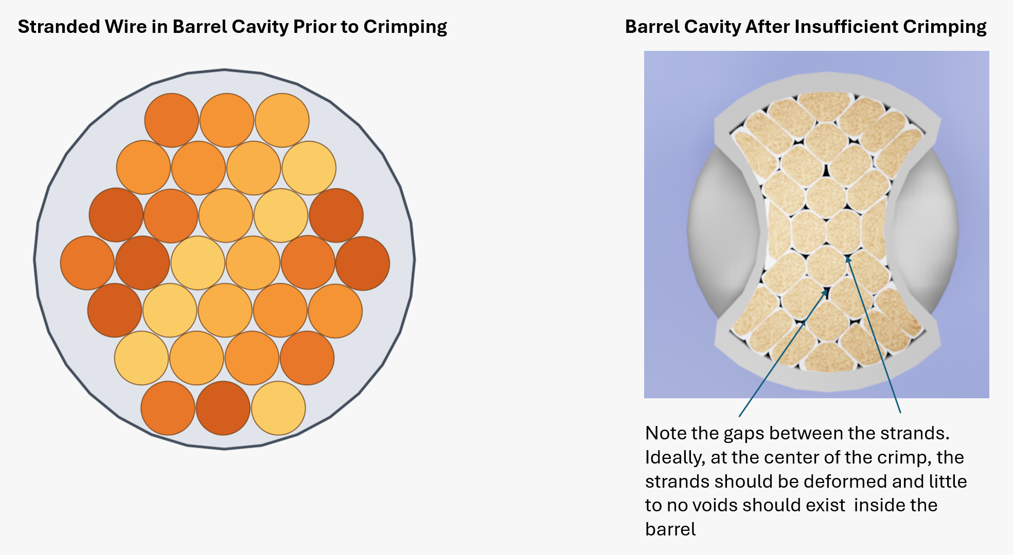
Simply put, when current passes through the conductor, resistive losses generate heat. The conductor, individual strands, terminal barrel, and interfaces within the crimp expand as their temperatures increase and contract as they cool. Repetition of this process can produce small changes in the mechanical contact conditions within the termination. Contact pressure can change, microscopic movement can occur, and newly exposed aluminum surfaces can oxidize. The result can be a progressive reduction in effective conductive contact area.
Once resistance begins increasing, the problem can become self-reinforcing. For a high-current circuit, even a relatively small increase in resistance can cause substantially more localized heating. This creates several potential system-level consequences.
First, increased termination resistance causes additional voltage drop. The termination is effectively a resistor in series with the connected equipment. As its resistance increases, a larger portion of the available system voltage is lost across the termination, and less voltage is delivered to the load. Depending on the circuit, this can cause degraded equipment operation, undervoltage conditions, or intermittent functionality.
Second, localized heating can damage adjacent insulation and other EWIS materials. If degradation continues, excessive heating can contribute to smoke or fire conditions.
Finally, a severely degraded connection can become unstable or intermittent. Separation between conducting surfaces while current is flowing can create conditions for series arcing. AS70991 current cycling is not an arc test and does not attempt to create an arc fault, but increasing resistance and localized overheating are warning signs of a deteriorating connection that should be identified before the termination progresses to that condition.
This is why simply confirming that a terminal conducts current is insufficient. The more important question is whether it continues to behave as a stable, low-resistance connection after repeated thermal cycling.
Preparing the Current-Cycling Samples
For qualification testing, AS70991 assigns six terminals to the current-cycling group. The terminals are crimped to each end of three 24-inch wire lengths and suspended horizontally in a draft-free chamber.
Before cycling begins, each test specimen is subjected to the specified voltage-drop test to establish its initial condition. The specimens are then connected in series with the power source using new 6-foot leads terminated with terminals identical to those being evaluated.
Thermocouples are then placed on the samples, on the terminals, and on the conductors. These temperature measurement locations are important because the AS70991 standard does not define the current-cycling exposure simply by amperage. Each cycle is characterized by a target temperature rather than a target current value.
Current-Cycling Test
During the test, the two most important values are the temperature and voltage drop. For a properly performing termination, the conductor should be the primary source of resistive heating. The larger terminal barrel should not become the dominant hot spot. AS70991 therefore requires the terminal temperature to remain at least 10 °C below the conductor temperature for any given cycle.
If terminal resistance begins increasing, additional heating occurs within the crimp. The barrel temperature rises relative to the conductor, causing the required thermal margin to decrease.
The second indicator is voltage-drop stability. AS70991 requires voltage-drop measurements late in the test, after cycles 60, 70, and 80. The measured values must remain within the applicable after-test limits in Table 1, and the difference between the cycle-60 and cycle-80 voltage-drop values cannot exceed 20%.
These two measurements provide complementary information. Temperature identifies whether the termination is becoming a localized heat source, while voltage drop identifies whether the electrical resistance of the connection is increasing.
The 80-Cycle Test
AS70991 requires a total of 80 cycles. Each cycle lasts 1.5 hours:
- Current is applied for 1 hour.
- Current is removed for 30 minutes, allowing the samples to cool at the ambient chamber temperature.
The conductor temperature is progressively increased during the test:
| Cycles | Conductor Temperature |
|---|---|
| 1–10 | 130 °C ± 2 °C |
| 11–20 | 140 °C ± 2 °C |
| 21–30 | 150 °C ± 2 °C |
| 31–40 | 160 °C ± 2 °C |
| 41–50 | 170 °C ± 2 °C |
| 51–80 | 180 °C ± 2 °C |
The applied current is adjusted as necessary to hold the conductor at the required temperature. The test is sometimes described as progressively “stepping up the current,” but technically it is the temperature requirement that increases. More current will generally be required to reach the higher conductor temperatures, but the specification controls the resulting conductor temperature rather than prescribing a sequence of amperage values.
The samples also are not required to return completely to room temperature between cycles. AS70991 specifies a 30-minute current-off period during which the specimens cool at ambient chamber temperature.
Interpreting the Results
A deteriorating termination will rarely begin with a dramatic open circuit. More often, degradation appears gradually. One terminal may begin operating slightly warmer than the others. Its terminal-to-conductor temperature margin may decrease over successive cycles. Voltage drop may also begin trending upward.
These trends can indicate that effective contact area within the crimp is decreasing and that more power is being dissipated at the termination. However, current-cycling tests also require careful test control. Changes in airflow, thermocouple attachment, power-source behavior, or resistance elsewhere in the series circuit can affect the results. For this reason, recording the complete thermal and electrical history of the test is valuable rather than relying only on the final acceptance measurements.
Conclusion
AS70991 current cycling is more than a high-current endurance test. It challenges the electrical interface inside an aluminum crimp by repeatedly heating and cooling the termination while monitoring for evidence of degradation. The test's 80-cycle progression from 130 °C to 180 °C creates a demanding thermal environment intended to reveal weaknesses that may not be apparent from initial inspection or mechanical testing.
Through this testing, an answer is generated for the question, “Does the termination remain a stable, low-resistance electrical junction after repeated thermal cycling?” By monitoring both terminal temperature and voltage drop, this approach provides two useful indicators of that stability. For aircraft electrical systems where termination degradation can lead to voltage loss, overheating, smoke, fire, or ultimately series arcing, that is an important capability to demonstrate before the component enters service.
If this method is used for the assessment of other types of terminations, the goal should be clear when setting performance requirements: seek to develop criteria that will ensure reliable performance at least through a major maintenance milestone. For commercial aircraft, this may be during heavy maintenance, such as D-checks. For military aircraft, this may be a number of flight hours or years in service.