
Creepage and Clearance
High voltage systems on aircraft will be more commonplace as the eVTOL market “takes-off.” One safety aspect that often comes up is the separation of the high voltage; often, this comes down to creepage and clearance distance of these systems. These distances are used on static conductive points on surfaces and come with the following limitations:
- These are not representative of separation distances in volumes other than air.
- Creepage and clearance should not be used to identify the safe separation distance of EWIS components in the instance of an arcing event; SAE AIR 6982 (which is in draft stage) will provide guidance on safe separation testing and practice in this case.
- At the time of this article, no standards have been developed for aerospace applications to define clearance and creepage distance.
- Industrial standards are relied on for distance estimations and must be verified through testing in high altitude conditions.
What are Creepage and Clearance Distances?
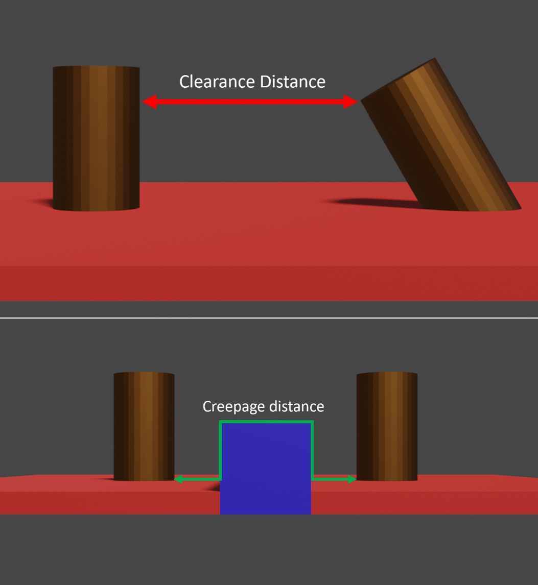
Clearance distance is the minimum separation distance between two conductive parts in air. This distance is based on the shortest line of sight between two conductive parts. Creepage distance is the minimum separation distance of two conductive parts along the surface of a solid insulating material.
Factors that Affect Creepage and Clearance
Voltage
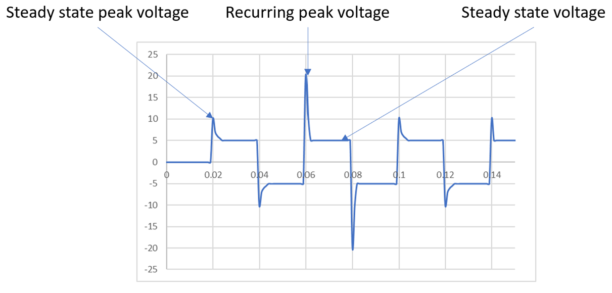
When considering voltage, the system steady-state voltage is not enough to calculate creepage and clearance distances. The steady state peak voltage, recurring peak voltage, and any transients must be factored in to prevent any accidental flashover. Steady state peak voltage is defined as the maximum voltage that is typically associated with the steady state working voltage. The recurring peak voltage is the maximum voltage periodically seen from distortions in an AC power source when converted to a DC output. Transients are distinguished by being very short lived and heavily damped overvoltages.
Altitude
When altitude increases, pressure decreases and the susceptibility of air to breakdown increases until the pressure reaches near vacuum conditions. This follows the trend established in Paschen’s curve. As altitude increases, the susceptibility for partial discharge also increases, which can reduce the lifetime of EWIS components
Pollution
Creepage and clearance distance cannot be evaluated in the presence of pollution beyond a certain level. When the open-air environment or insulating surface is coated in dust and/or moisture, then a conductive path can be made, which can result in electrical shorting events. If the area is saturated in pollution, then the pollution acts as a medium for which electrons can flow between electrodes. Below this threshold, some standards do provide guidance on the impact that pollution can have on creepage and clearance.
Insulation Materials
The insulating material separating two circuits (or in the case of the accompanying images, holding the electrodes in place), will mostly affect creepage distance, although some consideration should be given to clearance if the insulating materials will influence field conditions. One common mode of evaluating an insulating material’s ability to withstand high voltage is the comparative tracking index test. This test is used to evaluate a material’s ability to withstand carbon tracking in the presence of a contaminant at relatively low voltage.
The topography of an insulating surface between electrodes can also influence the creepage distance. Use of barriers between electrodes can allow for shorter separation distances as the electric field is disrupted, causing a larger creepage distance.
Other Factors
If the generated electric field between two conductors is inhomogeneous, then the clearance must be increased by a larger separation distance than if the field was homogenous. An example of a homogenous field can be created by using oppositely charged parallel plates and an inhomogeneous field can be produced by similarly charged point-like conductors.
IEC 60664-1
The title for IEC 60664-1, “Insulation coordination for equipment within low-voltage supply systems,” is a bit counterintuitive since high voltage for aerospace as defined by the SAE AE-10 committee starts at 425VAC (600VDC). IEC 60664-1 is an industrial standard, which puts the low voltage threshold between 50VAC (120VDC) and 1000VAC (1500VDC). Below and above these voltages are classified as Extra Low Voltage and High Voltage respectively.
IEC 60664-1 will likely be heavily referenced in the corresponding SAE AE-10 ARP document as the standard has altitude corrections for up to 20000 meters (65617 feet).
Wrap Up
The opportunities that are made possible on aircraft with the use of high voltage systems are plenty. Of course, how the systems are deployed will be limited based on electrostatics and the material properties of the insulators. Both the creepage and clearance distance of EWIS components, particularly at connection points, will be a concept that every EWIS engineer will become familiar with. How the standards evolve to meet these challenges is still to be determined, but as the industry moves forward, Lectromec’s high voltage experience and testing capabilities will be ready to help. Contact us to find out how we can help your project.